

A Savelyev DYNAMIC POSITIONING SYSTEM
.pdfDynamic Positioning System Chapter 4 |
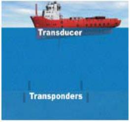
POSITION MEASUREMENT EQUIPMENT |
vessel's bottom, and a transponder located on the seabed.
Position measurements are based upon range and direction data determined from transponder replies resulting from interrogation. Up to five transponders can be interrogated in turn within the same area. Simultaneous use of multiple transponders is made possible by utilizing different interrogation and reply frequencies for each transponder.
The system measures the range of a transponder relative to the transducer by measuring the time elapsed between transmission of the interrogation signal and reception of the reply. This time lapse is made up of the through-water return time of the acoustic signal plus the turnaround time within the transponder. This latter is a fixed known value, and once allowed for, the distance, or Slant Range may be deduced.
The direction of the transponder is measured at the transducer as the source direction of the reply signal. This is determined from time-phase comparisons made between pairs of transducer receiving elements within the transducer head. Typically, 48 elements are used to make up the receiving unit within a transducer.
In a typical positioning mode, the processor commands the transceiver to transmit the interrogation signal. The transponder reply is detected by the transceiver which measures the time delay and the time-phase data. This data is passed to the processor to allow determination of slant range and direction. This information is combined with roll and pitch values obtained from the VRS in order to obtain information referenced to the vessel co-ordinate frame. Positioning data is shown on a display in terms of a graphic (map) display of vessel and transponder positions, and in the form of tabulated alphanumeric.
SHORT BASELINE SYSTEMS (SBL)
An array of transducers (hydrophones) are installed under the DP vessel. And, the distances between transducers are used as baselines.
A transponder positioned on the seabed transmits periodic pulses at a known frequency. And, the time difference between transmission and reception at three or more transducers is used to compute the vessel's position relative to the transponder.
LONG BASELINE SYSTEMS (LBL)
An array of three or more transponders are positioned on the seabed. (Four or more are used to give an element of redundancy.) Because the transponders are not attached to the moving vessel, the system can operate independently of VRU input, eliminating many problems associated with vessel motion.
Distances between transponders are used as baselines.
A single transducer under the DP vessel communicates with the array of transponders. And, only the range is determined. In other words, the DP vessel's position relative to the transponders is computed. Since the depth of the transducer is a known variable, using
- 2 -
Dynamic Positioning System Chapter 4 |
POSITION MEASUREMENT EQUIPMENT |
|||
this provides a further improvement |
|
|||
in position quality. If the object to be |
|
|||
positioned is an ROV and the depth is |
|
|||
Not accurately known, or variable, |
|
|||
then a further unknown quantity must |
|
|||
be calculated, requiring additional |
|
|||
range measurements. |
LBL |
is |
|
|
generally used |
in |
deepwater |
|
|
(> 1000m) drilling operations. |
|
|
||
Angle measurements are not required |
|
|||
at the transducer. Because of this a |
|
|||
major source of error, angular |
|
|||
distortion in reply signal paths due to |
|
|||
ray bending or |
refraction, |
is |
|
|
eliminated. Errors in range measurements caused by ray bending are less significant. The accuracy achievable is the major advantage of the LBL system over other HPR variants. The elimination of the need for attitude input from VRS also increases accuracy compared to USBL and SBL systems.
ADVANTAGES OF HPRS
Self contained position measurement equipment.
HPRs can be left on the seabed to provide reference for the DP vessel to returned to. HPRs can also serve as markers for equipments on the seabed.
Relatively high accuracy.
More options to suite prevailing DP operations. For example LBL, SBL, USBL, or SSBL.
LIMITATIONS OF HPRS
Roll and pitch affect the angle measured at the transducer head. Therefore, the angle must be corrected using input from VRU for accurate position determination.
Turbulence from the vessel's thrusters, noise, and poor acoustic conditions can cause
inaccuracy in HPR positioning.
HPR signals "spreads" with increased distance. Hence, accuracy is reduced in very deep
water.
Attenuation causes HPR signals to be absorbed by water. The frequency of transmission, water pressure, salinity, an temperature influence the amount of absorption.
HPR signals experience refraction (bending) during transmission. Speed of propagation, layers in the water column, water temperature, pressure, and salinity influence refraction.
- 3 -
Dynamic Positioning System Chapter 4 |
POSITION MEASUREMENT EQUIPMENT |
ARTEMIS
PRINCIPLES AND OPERATION OF ARTEMIS
Artemis is the trade name
for a
positioning system developed by Christian Huygenslaboritorium BV.
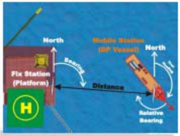
Principle of this system is based on
getting the range and bearing of a
movable vessel from a known fixed
position.
Procedure for setting up Artemis:
One directional antenna is mounted on a drilling rig, platform, or other fixed structure. The other directional antenna is mounted on the DP vessel. Operational control is initiate from the DP vessel.
Both antennas are aligned and "locked". A microwave link is then established between them to facilitate data transfer.
The range or distance is measured at the DP vessel based on the time difference between emission and return of a signal.
The bearing or direction of the DP vessel is measured at the fixed structure.
O When a fixed structure is unavailable, a beacon may be used in place of an antenna on a floating structure. For example, Offshore Loading Terminal (OLT). In this case, it is impractical to measure bearing at the floating structure. Hence, bearing determination is made at the DP vessel.
ADVANTAGES OF ARTEMIS
Provides geographic position reference. Unlike many PMEs that only provide relative position.
Not affected by precipitation because it operates on 9.2 - 9.3 GHz.
Localized position measurement equipment. Therefore, it is convenient for customization to suite the DP peration.
Relatively high accuracy. Long Range.
LIMITATIONS OF ARTEMIS
A correction must be factored into the DP system for the antenna offset from the center of gravity of the vessel. The range and bearing data is based on antenna to antenna.
X-bank (3cm) radar signal interferes with Artemis signal despite the fact that the 3cm radar uses horizontally polarized waves while Artemis uses vertically polarized waves.
Correction must also be applied to Artemis data to compensate for rolling and pitching of
- 4 -
Dynamic Positioning System Chapter 4 |
POSITION MEASUREMENT EQUIPMENT |
the DP vessel.
Excessive heat on the oil rig or platform may interfere with the Artemis if within close proximity.
Artemis is affected by line-of-sight obstruction.
The fixed unit has to be configured and calibrated correctly. Personnel on fixed unit may be needed to set up unit on their end. Vulnerable to power supply problem at Fixed end.
TAUT WIRE
Short range position reference useful where a vessel may spend long periods in a static location, and where the water depth is limited. Taut Wire System is useful for DP operation in the same location for an extended period of time, where the water is not too deep. There are two types:
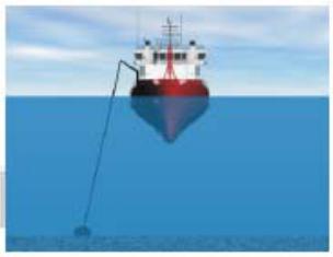
VERTICAL TAUT WIRE
A crane assembly is fitted near the side
of the vessel.
A depressor weight is suspended by a wire attached to constanttension
winch.
The depressor weight is lower to the seabed.
Constant tension is set on the winch. The winch adjusts the length of the
wire to maintain constant tension as
the vessel wanders.
Angle sensors (inclinameters) at the end of the boom measure the angle of
the wire.
The length and angle of the wire deployed indicate the position of the sensor relative to the depressor with. This information is corrected for the vessel pitch and roll. And, used
to determine the vessel's position. HORIZONTAL OR SURFACE TAUT WIRE
Because it is not a long-range system, it is generally used for relative DP when operating near another vessel or fixed structure, i.e. crane barge, accommodation "Floatel" operations.
The principle of operation is basically similar to the vertical taut wire. However, the wire is attached to a prominent point on a fixed structure instead of a depressor weight.
TAUT WIRE REFERENCE DISPLAY
After the Taut Wire has been deployed and accepted as a position reference in the DP system, a display screen with pertinent Taut Wire information is accessible. Information on the screen will usually include the position of the depressor weight, angular and structural limits, water depth, etc.
ADVANTAGES OF TAUT WIRE Quick and easy to deploy system.
Mechanical system, therefore, it can be repaired on board when necessary. Very accurate in moderate water depth.
- 5 -
Dynamic Positioning System Chapter 4 |
POSITION MEASUREMENT EQUIPMENT |
All weather operation is possible.
Localized position measurement equipment. Good reliability.
Assistance from external sources to set up or operate is unneeded. LIMITATIONS OF TAUT WIRE
The system can be affected by strong current. Accuracy deteriorates in very deep water. Short range only, especially in shallow water.
Adversely affected by surface debris or ice conditions. Relative position measuring system only.
Wire may hamper ROB, diver or other underwater activity.
Taut wire has to be redeployed each time vessel has to shift position. Possibility of positional error caused by weight dragging.
Wire may be fouled by ROV, divers, or other underwater activity. Susceptible to mechanical damage.
Reliant on vessel main power (not normally connected to UPS), and cooling.
- 6 -
Dynamic Positioning System Chapter 4 |
POSITION MEASUREMENT EQUIPMENT |
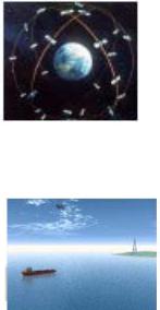
GLOBAL POSITIONING SYSTEM (GPS)
GPS is a satellite-based, passive-ranging navigation system which provides latitude, longitude, and attitude data worldwide. GPS consists of 21 satellites, with 3 spares.
The GPS satellite system is controlled by the US Department of Defense. The US Department of Defense reserves the right to turn-off GPS completely or to reduce the 20m civilian accuracy for civilian use is still notsufficient for most DP operations.
The GPS accuracy generally available for civilian use (Standard Positioning Service) is within 20m.
Differential corrections are applied to GPS data to improve accuracy for DP use.
Fixed reference stations are located at strategic positions on earth.
Each reference station uses the data from GPS satellite and its known position to compute a correction for each satellite.
The reference stations transmit the corrections to the vessel via a data link.
The vessel's GPS receiver automatically applies the correction to position data received form the satellites.
DIFFERENTIAL GLOBAL POSITIONING SYSTEM (DGPS)
Q Differential GPS improves civilian position accuracy to 1m - 5m. O Differential Correction Network.
O Multiple reference stations provide differential information.
O Network DGPs reference stations offer more stability and accuracy compare with data from an individual reference station.
O Differential Correction Network.
^ DGPs network stations generally improve civilian position accuracy to 1m3m.
O The notion of Available Quality is designed to simplify DGPs status information available to the DPO.
O The International Marine Contractors Association (IMCA) proposed a DP Quality Indicator (DQI) system that consists of numeric values from 1 to 9 to represent the operating status, reliability, precision and redundancy of DGPs data. The larger the value, the higher the DGPs data available. Generally, 5 to 9 is adequate for DP operations.
ADVANTAGES OF DGPS
Relatively high accuracy.
Many satellite constellations available.
Global coverage with the exception of Polar regions.
Proximity to drilling platforms or oil rigs (these structures interfere with satellite signals and differential corrections).
LIMITATIONS OF DGPS
Accuracy affected by solar flares activities.
Accuracy deteriorates with increase distance from reference stations.
Drilling platforms, oil rigs or other large structures interfere with satellite signals and differential corrections.
Additional cost for differential correction.
- 7 -
Dynamic Positioning System Chapter 4 |
POSITION MEASUREMENT EQUIPMENT |
RELATIVE GPS
A procedure used to dynamically position a vessel off a moving, instead of a fixed position. DP shutter tankers often us relative GPS when loading via a bow hose form the stern of a Floating Production Storage and Offloading (FPSO) vessel.
The FPSO may be turret moored to allow it to weathervane. Consequently, heading and position wandering occur. The stern of the FPSO moves to reflect heading and position change. Thus, the shutter tanker is faced with a complicated dynamic positioning situation.
DARPs (Differential, Absolute and Relative Positioning System )placed on the FPSO is used to resolve the complications resulting from relative dynamic positioning.
THE FPSO uses Network DGPS to get and absolute position. And, relays its position information to the shutter tanker via a UHF link.
The shutter tanker's computer uses the UHF data to determine the range and bearing from the stern of the FPSO. This position reference information is used by the shutter tanker's DP control system for relative Dynamic Positioning.
LASER-BASED SYSTEMS
Laser System is useful for DP operation conducted in the same location or slow moving vessel.
LASER SETUP
A typical setup scenario for laser based systems is for the vessel to back-up to the rig or structure and place targets. The vessel would then move away from the rig or structure and select laser on the DP system and wait for the signal to connect.
NOTE: There have been instances where workers with reflective tape have caused the system to wander.
ADVANTAGES OF LASER
Laser is effective and accurate when operating within close proximity to oil rigs, platforms, or other la: jc structures that may interfere with DGPS signal.
Quick and easy to set up. Proximity to drilling platforms or oil rigs (these structures interfere with satellite signals and differential corrections).
LIMITATIONS OF LASER
Laser is affected b piv ;pitation in the atmosphere.
The range of the lasc: is limited to a few thousand meters.
Reflective targets arc required on fixed structures.
There are two types of laser s; stems commonly used:
FANBEAM
The Fanbeam system ;s an alternative short range laser based positioning and tracking system. The system consists of a vessel borne laser unit and a reflector, providing range
and bearing.
A reflector positioned n a fixed or movable structure reflects the light.
The laser unit receive^ 'he reflection. And, the image and bearing are determined. A VRU for pitch and i II compensation is needed.
Advantages Of Fanbeam
Low cost compared to other measurement equipments installation.
Target does not require any support services once installed.
Targets in expensive to make, i.e. plywood, pvc.
High accuracy within T cm.
- 8 -

Dynamic Positioning System Chapter 4 |
POSITION MEASUREMENT EQUIPMENT |
Limitations Of A Fanbeam
Not as effective when the sun shines directly into the lenses. The lenses can be affected by condensation, rain, and salt spray.
The system may suffer interference from reflective items in the area of the target. Practical, useful range for DP is around 200-250 meters.
CYSCAN
CyScan is a short-range, laser-based, high precision positioning and tracking system consisting of a rotating laser placed on a stabilized platform which compensates for pitch and roll.
Three or more retro-reflective targets are fitted on the DP vessel at defined spacing along a baseline.
The laser emits a pulse of light which is reflected back. The time interval between emission and reception: and angle are used to determine the DP vessel's position relative to the laser.
POOLING AND WEIGHTING PRS DATA
Pooling is the process of combining data from Position Measuring Equipments (PMEs) when two or more PMEs are activated, to optimize the overall position data.
The pooling process is based on Weighted averaging to use the advantages of each activated PME.
The limitations of each APME is minimized by the combined advantages.
PME CHARACTERISTICS
Type |
Range |
Max. Depth |
Accuracy |
HPR |
5 times water depth |
4,000m |
1 -2% of water depth |
Artemis |
30k::i |
n/a |
+or-lm |
Taut Wire |
25% of water depth |
500m |
2% of water depth |
DGPS |
Unlimited |
n/a |
+or-3m |
Laser |
Up to 200 an |
n/a |
Less than .5m |
|
250'- practical DP use |
|
|
|
|
|
|
GLONASS SYSTEM
Global Navigation Satellite System (GLONASS) is the Russian version of the United States' GPS system
O GLONASS, like GPS, uses pseudo-range measurement from time and satellites position to determine position.
GLONASS satellites I h orbital inclination of 65 degrees offer better position coverage in higher latitudes, compared to GPS constellation (55 degrees).
Some GLONASS satellites are not consistently operational for position determination.
- 9 -
Dynamic Positioning System Chapter 4 |
POSITION MEASUREMENT EQUIPMENT |
Hence, GLONASS is not always available for continuous position update. ^ Combined GPS/GI receivers use both satellites systems. This ability increases
the number of satellites available for r it ion coverage.
Global Navigation Satellite System (GLONASS) is the Russian version of the United States’ GPS system.
GLONASS, like GPS, uses pseudo-range measurement from time and satellites position to determine position.
GLONASS satellites high orbital inclination of 65 degrees offer better position coverage in higher latitudes, compared to GPS constellation (55 degrees).
Some GLONASS satellites are not consistently operational for position determination. Hence, GLONASS is not always available for continuous position update.
Combined GPS/GLONASS receivers use both satellites systems. This ability increases the number of satellites available for position coverage.
PRINCIPLE OF EMULATION AND LIMITATIONS
Emulation is the process of interfacing data from position references in the DP system.
LIMITATIONS OF EMULATION
Since most DP systems are proprietary, any update to the system has to be factored in to the emulation process by the manufacturer of the DP system.
Bypassing this requirement may result in unsatisfactory results.
- 10 -
Dynamic Positioning System Chapter 5 |
ENVIRONMENT SENSORS |
ENVIRONMENT SENSORS AND ANCILLARY EQUIPMENT
VERTICAL REFERENCE FOR DP INPUT
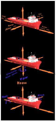
Dynamic Positioning maintains a vessel’s position by controlling Surge and Sway.
Dynamic Positioning maintains heading by controlling Yaw. Heave, Pitch, and Roll, on the other hand, are monitored to enhance position data from Position Measuring Equipments (PMEs).
As the vessel rolls or pitches, positions of PMEs are offset from the center of gravity of the vessel. This offset may also be interpreted by the DP system as an actual position change of the vessel.
Some vessels such as cruise ships may have stabilizers to damping roll.
Vertical Reference Sensor (VRS), Vertical Reference Unit (VRU) or a Motion Reference Unit (MRU) is fitted in the DP vessel to measure pitch, roll, and heave.
The terms Vertical Reference Sensors )VRS) and Vertical Reference Unit (VRU) are interchangeable.
The DP control system uses data from VRS, VRU, or MRU to compensate for the offset of various position reference sensors from the centre of gravity of the vessel.
For Dynamic Positioning purposes, the effects of pitch and roll are more critical to position keeping than heave. A simple VRS
consists of a damped pendulum in a chamber containing a viscous fluid. Detector coils converts the position of the pendulum to an analogue voltage to represent angles of roll and pitch. A more complex VRS has facility to measure heave. Motion Reference Unit (MRU), on the other hand, uses linear accelerometers to measure accelerations and calculates inclination angles.
GYRO COMPASS IN A DP SYSTEM
HEADING REFERENCE
Gyro compass provides heading data to the DP system.
DP vessels that require redundancy have two or more gyro compasses.
If only two gyro compasses are installed, the DP system is limited to monitoring the difference in heading data. And, issuing a warning, if this difference exceeds a certain value. If three gyro compasses are fitted, the DP system can use two-out-of-three voting to determine a gyro failure, and give a warning accordingly.
Heading reference may also be available from strategically positioned DGPS receivers and motion sensors.
- 1 -