

A Savelyev DYNAMIC POSITIONING SYSTEM
.pdf
|
Dynamic Positioning System Chapter 3 |
PRACTICAL OPERATION OF A DP SYSTEM |
|
To set a new point of positioning:
Press the AUTO Softkey in the POS Group, after that the Position Setpoint Editor appears. Set. OR,
Use Position Mode Parameters Window:
Press the Param Softkey in the Windows Select Area to load the Parameters Window. Select heading Mode Parameters Window (Pos Softkey).
Press the Set Softkey, after that the Position Setpoint Editor appears. Set desired Position Setpoint value (see description below).
Press the Apply Softkey in the Position Mode Parameters Window.
The Position Setpoint Editor allows the following actions:
HOLD POSITION
To hold the actual vessel Lat. and Long. as the point of positioning (Position Setpoint):
Press the Hold Softkey. The actual vessel Lat. and Long. values appear in the Editing Field. Press the OK Softkey for set point of positioning acknowledgement.
SET POSITION
To set a new point of positioning:
Enter desired Positioning Setpoint value into Editing Field using Numeric Keypad. Press the OK Softkey for set point of positioning acknowledgement. The Hold POS LED indicator is illuminated on the active Control Panel.
NOTE: If the system is in the J/DP Mode, an operator can transfer the system to the Auto Position Mode holding the actual vessel position pressing the Hold POS Pushbutton with the non-illuminated LED Indicator on the Control Panels.
OFFSET POSITION
To input the new point of positioning as an offset of Actual Position Setpoint:
Press the Offset Softkey.
Choose TRUE or REL offset entering.
Enter desired Position Setpoint offset.
Press the OK Softkey for acknowledgement.
NOTE: It won't be possible to set other characteristics in the Parameters Window or to load a different mode if the Position Setpoint Editor is active.
HEADING CONTROL ADJUSTMENT
Heading Gain - To set Heading gain:
Press Param Softkey in the Windows Select Area to load the Parameters Window. Select Heading Mode Parameters Window (HDG Softkey).
Using < and > buttons set necessary values from the range: 6, 12, 18, 24, 30, 60, 120. Press the Apply Softkey in the Heading Mode Parameters Window to acknowledge.
- 11 -
|
Dynamic Positioning System Chapter 3 |
PRACTICAL OPERATION OF A DP SYSTEM |
|
Heading Limit.
POSITION CONTROL ADJUSTMENT
Position Gain - To set Position gain:
Press Param Softkey in the Windows Select Area to load the Parameters Window. Select Position Mode Parameters Window (Pos Softkey).
Using < and > buttons set necessary values from the range: 1..100.
Press the Apply Softkey in the Position Mode Parameters Window to acknowledge. Position Limit.
Vessel Speed Limit.
THRUSTER LIMITS
To set Thruster Limits:
Press Param Softkey in the Windows Select Area to load the Parameters Window. Select TAL Mode Parameters Window (Thr Lim Softkey).
Using < and > buttons set required limit values for each actuator from the range: 1-100%, and for Rudders: 0°..65°.
Press the Apply Softkey in the TAL Mode Parameters Window to acknowledge.
In the J/DP Mode set limits are indicated by red triangles in the Auto/Manual Thruster Window.
POWER LIMITS
To set Power Limits:
Press Param Softkey in the Windows Select Area to load the Parameters Window. Select Power Limits Parameters Window (Pow Lim Softkey).
Using < and > buttons set required limit values for each thruster, engine, or generator from the range: 1-100%.
Press the Apply Softkey in the Power Limits Parameters Window to acknowledge.
In the J/DP Mode, set limits are indicated by red lines in the Power Monitoring Window.
ROV FOLLOW PARAMETERS ADJUSTMENT
To set ROV Follow Parameters:
Press the Param Softkey in the Windows Select Area to load the Parameters Window. Select ROV Follow Mode Parameters Window (ROV Softkey).
Set Reaction Radius and Stop Radius for ROV Following. Set ROV Follow speed.
Press the Apply Softkey in the ROV Follow Mode Parameters Window to acknowledge.
TRACK CONTROL (LOW SPEED) MODE PARAMETERS ADJUSTMENT
- 12 -
|
Dynamic Positioning System Chapter 3 |
PRACTICAL OPERATION OF A DP SYSTEM |
|
To set ROV Follow Parameters:
Press the Param Softkey in the Windows Select Area to load the Parameters Window. Select Track Control (Low Speed) Mode Parameters Window (TRACK Softkey). Select Track Control Strategy.
Set Vessel Speed for Low Tracking. Set Off track Limit.
Set Track Gain.
Press the Apply Softkey in the Track Control (Low Speed) Mode Parameters Window to acknowledge.
ROUTE LIST EDITING
Open the Select Route window for the Route List modifying.
NEW ROUTE CREATION
To create a new route:
Using the t and -I softkeys, select a row in the Route List, where you wish to insert a new route.
Press the Add Route control button.
A new row appears above the selected one. By default a new route has the New Route name and Low Speed status. A waypoint list of the new route is empty by default.
ROUTE EDITING
To edit route characteristics:
Using the t and -I- softkeys select a row in the Route List, which is necessary to edit. All
characteristics of the selected route are indicated in the lower part |
of the |
Select |
Route |
|
Window. |
|
|
|
|
Press the Edit Route control button. Control buttons of the lower part of the window |
|
|
||
become active and control buttons of the upper part of the window - inactive. |
|
|
|
|
To edit a name of the route, press the Route Name |
button. The |
Route |
Name |
Editor |
appears. Using the Alpha-numeric keypad, input the new |
name of the |
route |
and press the |
|
OK button for acknowledge. |
|
|
|
|
To change route status, press the Set Status control button. |
|
|
|
|
Using buttons Add Point, Edit Point, and Del Point, edit a waypoint list of the route (see
below).
Press the OK button for acknowledgement of new characteristics of the selected route.
ROUTE REMOVAL
To remove a route from the Route List, do the following:
Using the t and 4 softkeys select a route in the Route List, which you wish to delete. Press the Del Route control button.
- 13 -
|
Dynamic Positioning System Chapter 3 |
PRACTICAL OPERATION OF A DP SYSTEM |
|
WAYPOINT LIST EDITING
NEW WAYPOINT CREATION
To add a new waypoint to the WP List:
Using the t and -I softkeys, select a row in the WP List, where you wish to insert a waypoint.
Press the Add Point control button.
A new row appears above the selected one. By default coordinates of the next waypoint are set as new waypoint coordinates.
If the added waypoint is the first, coordinates of the Motion Plot center are set as new waypoint coordinates.
WAYPOINT COORDINATES EDITING
To edit WP coordinates:
Using the t and 4- softkeys select a waypoint, which coordinates should be edited. Press the Edit Point control button.
The |
Waypoint Editor |
appears. Using the numeric keypad input the new WP coordinates (similar |
to |
Position Setpoint |
editing, see items 5.7.4.1 - 5.7.4.3) and press the OK button for |
acknowledge. |
|
|
WAYPOINT REMOVAL
To remove a WP from the Waypoint List:
Using the t and -I softkeys select a waypoint, where you wish to delete.
Press the Del Point control button.
AP CONTROL MODES
The Autopilot Mode is used for Heading Control when underway moving ahead. Propellers are
working synchronously. Vessel Speed control |
is provided by propeller RPM control from the |
Bridge Control Station. Synchronized rudders |
controlled by the IVCS 2000 provide heading |
Control. The following modes are available: |
|
MANUAL COURSE KEEPING
Direct Manual Control of synchronized rudders, using the Rotary Knob. To enter this mode: Press the AP Softkey on the touch screen (if it is not already illuminated). After pressing,
- 14 -
|
Dynamic Positioning System Chapter 3 |
PRACTICAL OPERATION OF A DP SYSTEM |
|
it blinks.
Press the ENTER Pushbutton on Control panel or Joystick Pushbutton or the ENTER Control Softkey to acknowledge (after that the AP Softkey becomes bright green). Select Manual Heading Mode, similar to AP Mode selection (the Softkey MAN in HDG Group).
Maneuver the vessel by the Knob to set desired rudder angle (see the Hold Plot Window).
If the system is in A/P Mode, an operator can |
transfer the system from the Auto Heading |
Mode |
to the Manual Heading Mode holding the |
Hold HDG Pushbutton with illuminated |
LED |
Indicators on the active Control Panel. |
|
|
AUTO COURSE KEEPING |
|
|
Automatic holding of Heading. To enter this mode: |
|
|
Press the AP Softkey on the touch screen (if it is not already illuminated). After pressing
it blinks.
Press the ENTER Pushbutton on Control panel or Joystick Pushbutton or the ENTER Control Softkey to acknowledge (after that the A/P Softkey becomes bright green).
Select Auto Heading Mode, similar to A/P Mode selection (the AUTO Softkey in the HDG Group).
Set desired heading using the Heading Setpoint Editor.
If the system is in A/P Mode, an operator can transfer the system to the Auto Heading Mode holding the actual heading by momentarily pressing the Hold HDG Pushbutton with the nonilluminated LED Indicator on the active Control Panel.
TRACK CONTROL (HIGH SPEED) MODE |
|
|
|
|
This mode provides route following with automatic control of |
vessel |
heading. |
Operator |
using |
Engine Telegraph controls vessel speed along the track in this |
mode |
manually. |
To enter |
this |
mode: |
|
|
|
|
Press the AP Softkey on the touch screen (if it is not already illuminated). After pressing it blinks.
Press the ENTER Pushbutton on Control panel or Joystick Pushbutton or the ENTER Main Soft Key to acknowledge (after that the J/DP Softkey becomes bright green). Press the Select Windows Main Softkey and set the Select Route window (the Route softkey).
At this time the graphic presentation (polyline) of the current route from the Route List appears on the Motion Plot.
Select a route with High Speed status. Edit it if necessary. Or, create a new High Speed route.
Set the selected route as Active. At this time:
The selected route row color in the Select Route Window is changed to dark red. Graphic presentation of the selected Active route appears on the Motion Plot (dark red polyline).
Waypoint list of the selected Active route appears in the Track Control Window. Main Softkey TRACK in the POS group becomes active (bright green).
NOTE: If you occasionally set a route with the Low Speed status as Active, it won't be possible to load the Track Control (High Speed) Mode.
- 15 -
|
Dynamic Positioning System Chapter 3 |
PRACTICAL OPERATION OF A DP SYSTEM |
|
Set Track Control (High Speed) Mode parameters. It is possible to change set parameters at any moment during the IVCS 2000 operation.
To start High Speed Tracking, press the TRACK Main Softkey (POS Group).
To switch off the Track Control (High Speed) Mode, select any other IVCS 2000 Control Mode.
AP CONTROL ADJUSTMENT
Press Param Softkey in the Windows Select Area to load the Parameters Window. Select Auto Pilot Parameters Window (AP Softkey).
Using < and > buttons set required values: Rate of Turn from the range: 6, 12, 24,30,60,120°/min. Heading Limit from the range: 2,3,5,10,15,30°.
Heading Gain from the range: 1 .. 10.
Rudder Limit from the range: 5,10,15,20,25,30,35,40,45,50,55,65°. Rudder Dead Zone from the range: 0.1…3°.
Set Turn Radius for the Track Control (High Speed) Mode. Set Off Track Limit for the Track Control (High Speed) Mode. Set Track Gain.
Press the Apply Softkey in the View Setting Window to acknowledge.
DISPLAY ADJUSTMENT
Press Param Softkey in the Windows Select Area to load the Parameters Window. Select View Settings Window (View Softkey).
Using Change or <> buttons set required values: Grid On/Off.
Sub Grid On/Off.
Units (m, ft, cables, Lat. Long.). Palette Day/Night.
Auto View On/Off.
View True/Relative.
Scale 128 – 0.125.
Trace On/Off. Step 10,30,60,600,1800,3600 sec.
Press the Apply Softkey in the View Setting Window to acknowledge.
- 16 -
|
Dynamic Positioning System Chapter 3 |
PRACTICAL OPERATION OF A DP SYSTEM |
|
SIMULATOR OPERATIONS
INITIALIZATION
Carry out the following steps to operate the IVCS 2000, in the Simulator Mode: Load the IVCS 2000.
Select Simulator Mode in the Main Screen. Then, the Edit Starting Conditions Window
appears, where you should set initial conditions for.
Vessel Speed, Heading, and Position (Lat. Long) - Conditions Mode (the Conditions
Softkey).
Wind Speed, Wind Direction, Current Speed, Current Direction, Water Depth, Wave
Height, Wave Direction - Disturbance Mode (the Disturb Softkey).
To set the required value, press the Edit Softkey and corresponding Editor appears below
the Edit Starting Conditions Window.
Press the OK Softkey in Edit Starting Conditions Window for acknowledgement of set initial values and to load the IVCS 2000 in the Simulator Mode,
SIMULATION
After carrying out actions above, the IVCS 2000 is ready for operation in the Simulator Mode.
You can then, operate the same as in the Real Mode.
STATUS AND ALARM MESSAGE
The system provides an alarm report in the Alarm Window and Alarm Monitor.
To load the Alarm Window, select the Alarm Softkey in the Windows Select Area. To load the Alarm Monitor, press the Monitor Softkey in the Alarm Window or select Services -^ Alarm Monitor option in the Main Screen.
There are two independent alarm states:
Acknowledged / Not Acknowledged alarm. To acknowledge the current alarm, press the
ACK Softkey in the Alarm Window. Current / Past alarm.
Start Time of alarm - time when the alarm was generated by the 1VCS 2000.
Stop Time of alarm - time when an alarmed fault was cleared.
For example, if the Main Control Panel was accidentally disconnected, the system generates the alarm Main control panel: connection lost. The Start Time is time of alarm generation. This
alarm is current until the connection is restored and the Stop Time is time of restoration.
Also, information concerning the last current not acknowledged (or last not acknowledged)
alarm appears, in the Last Alarm/Message Line.
- 17 -
|
Dynamic Positioning System Chapter 3 |
PRACTICAL OPERATION OF A DP SYSTEM |
|
CONTROL MODES AND FUNCTIONS
BRIDGE CONTROL MODE
Provides vessel control from the Bridge Control Console, using Engine Telegraph Levers, Bow and Stern Thruster Control Levers, and Steering Levers Or Wheel. The 1VCS 2000 is in operation and is ready for control acceptance.
STANDBY CONTROL MODE
Provides vessel control through the 1VCS 2000. It is impossible to control from the bridge
control station. Manual independent control of all vessel actuators is provided in the standby
control mode. The IVCS 2001 enters this mode after been switched on. The system is ready to pass the control to the J/DP Mode or to Autopilot mode at any moment.
JDP CONTROL MODE
Provides control through the joystick or DP System. J/DP mode includes Heading
Control |
and |
Position Control. |
|
HEADING CONTROL
Vessel Heading Control is provided manually or automatically by means of control moment
generation. The operator is able to choose the following modes:
Manual Heading - provides control of vessel heading from the Main Control Panel or
Portable Control Panel by knob rotation, which generates a control moment. Auto Heading - used for automatically holding a selected heading. The following functions are available:
Hold Heading - holds current heading.
Set Heading - sets new course and steers to it, automatically.
Minimal Power Heading - automatic course holding based on a calculated heading,
which minimizes the disturbance due to the effects of wind, waves, and current. This results in minimum DP activity and minimum power consumption.
POSITION CONTROL
- 18 -
|
Dynamic Positioning System Chapter 3 |
PRACTICAL OPERATION OF A DP SYSTEM |
|
This mode provides control of athwartships and fore-aft vessel motion.
MANUAL POSITIONING (JOYSTICK MODE)
Controls the vessel positioning. Fore-aft and athwartships forces from propellers, rudders, and
thrusters are commanded by the joystick lever movement in two axes. It is used for vessel positioning at dock maneuvering, drilling rigs, etc.
AUTO POSITIONING
Automatic position-keeping mode maintains the vessel in a selected position. The following
functions are included:
Hold Position - holds present position.
Set Position - sets new position and move to it.
Offset Position - sets position, offset by a selected distance from another position.
SEMI-AUTOMATIC CONTROL
Most commonly used when mooring. The following functions are included:
Manual Surge & Auto Sway - joystick manual control of fore-aft motion (set heading direction) and automatic holding of athwartships position.
Auto Surge & Manual Sway - joystick manual control of athwartships motion and automatic holding of fore-aft position (set heading direction).
Manual Speed Vector - joystick control of vessel speed vector.
REMOTE OPERATED VEHICLE FOLLOWING
Enables the vessel to automatically follow a moving target (ROV - Remote Operated Vehicle)
and keeps the vessel at a constant position relative to the ROV. To operate this mode, the vessel
should be equipped with a Hydroacoustics Position Measurement Equipment for monitoring its
position relative to the ROV. The following Heading functions are available: Auto Heading:
Hold Heading - holds a current vessel heading when following an ROV.
Set Heading - sets new heading and holds it automatically when following an ROV.
System Selected Heading - ROV follow with heading directed to the moving target at all times.
Manual Heading - manual heading control by knob rotation.
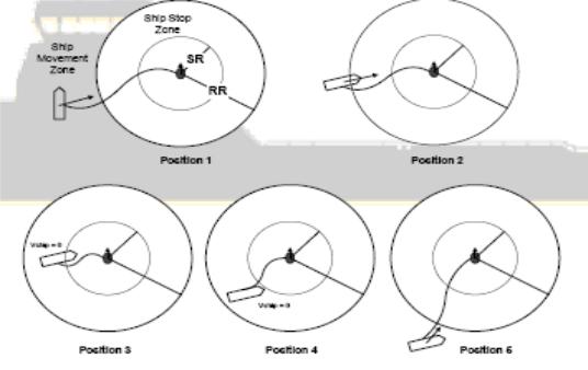
In the ROV Follow Mode the DPO sets:
Reaction Radius (RR) (Watch Circle) - defines a circle of operation, within which
the
ROV can move without causing the vessel to move. It only moves when it crosses
- 19 -
|
Dynamic Positioning System Chapter 3 |
PRACTICAL OPERATION OF A DP SYSTEM |
|
the
boundary of the circle of operation. The center of this circle is the ROV. Maximum value of ROV Follow Speed - a constant speed of vessel movement
when
following an ROV. A speed vector is always directed towards the ROV in this mode.
A Stop Radius (SR), which is automatically determined based on the Watch Circle and
defines a circle at which the vessels stops when entering it. The ROV is at the center of
this circle.
Position 1. The vessel is outside of the Reaction Radius (Watch Circle) and moving towards the
target. The target is moving forward.
Position 2. The vessel is moving towards the target, crossing the Watch Circle. The target is
moving forward.
Position 3. The vessel is inside the circle of operation. It has entered the Stop Radius and is
stopped. The target is moving forward.
Position 4. The vessel is inside the circle of operation. It does not move. The target is moving
forward.
Position 5. The vessel has crossed the circle of operation. It starts moving. The target is moving
forward.
TRACK CONTROL (LOW SPEED)
Vessel travels along the connecting line (leg) between two waypoints from the selected
- 20 -