

A Savelyev DYNAMIC POSITIONING SYSTEM
.pdfDynamic Positioning System Capter7 OPERATIONS USING DYNAMIC POSITIONING
In order to draw a worksite diagram based on UTM coordinates: Select the central meridian in the zone closest to your position. Plot the Northings for your position relative to the Equator.
Plot the Eastings for your position relative to the central meridian in your zone.
Caution: U.T.M. coordinates based on the central meridian in a zone will not align with coordinates for the same location based upon another central meridian. Draw all diagrams for the DP operation to the same projection and central meridian datum.
EMERGENCY AND CONTINGENCY
The dynamic nature and precision require of D
o operating procedures, prevailing circumstances, and experience to anticipate situations ld cause the DP vessel to loose pos
imate goal of emergency and contingency plans is to allow the vessel to safely terminate ration, and escape from the location
sibe blackout. If an escape is not possible, on a dive vessel for example, position and heading maintained.
Dynamic Positioning System Capter7 OPERATIONS USING DYNAMIC POSITIONING
CAPABILITY OF DP VESSELS
Assessing a vessel's DP capability is a prerequisite for determining whether the vessel can meet the demands of a particular operation. Several sources are available to help assess the DP vessel's capability:
XX FMEA (failure modes and effects analysis).
O ERN Numbers.
XX Capability Diagram. <X Footprint Plot.
The |
Capability |
Plot/Diagram |
|
contains |
results |
of the |
IVCS |
2000 |
Capability |
Analysis |
and |
allows an operator to set different
system |
configuration |
and |
select |
||
environmental |
conditions |
to |
|||
forecast |
the |
maximum |
weather |
||
conditions |
in |
which |
the |
vessel |
|
can |
maintain |
position |
and |
||
heading. |
|
By |
examining |
this |
|
window |
an |
operator |
can |
clearly |
|
see the current (or forecasted)
operational |
limits for |
current |
(or |
|
set) |
environmental |
conditions |
||
and |
select |
an optimal |
heading |
for |
most safe operations.
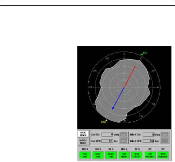
There are two modes of the Capability Diagram Window operation:
Real Mode - In this mode, the system indicates the maximum weather conditions in which the vessel is able to continue DP operation for current system configuration (thrusters set and maximum loading), actual current conditions (speed and direction), and actual wind direction. To operate the Capability Diagram Window in the Real Mode, press the Real Mode control button in the middle part of the window.
Hypothetic Mode - Forecast of the maximum weather conditions for which the vessel can maintain position and heading for set system configuration (thrusters set and maximum loading), set current conditions (speed and direction) and set wind direction. To operate the Capability Diagram Window in the Hypothetic Mode, press the Hypot Mode control button in the middle part of the window.
The Capability Diagram Window has the following structure:
The upper part of the window contains the Capability Plot where the following information is indicated:
Circle Grid, where each of concentric circles points a wind speed value and rays determine relative vessel heading direction.
Blue-red arrow points North direction .
Wind direction (actual for Real Mode and set for Hypothetic Mode) - yellow triangle with symbols HW.
Current direction (actual for Real Mode and set for Hypothetic Mode) - green triangle with symbols HC.
Area, within which the vessel can maintain position and heading depending on wind speed.
This area is determined by the actual current speed and direction and the actual wind direction for the Real Mode and by set current speed and direction and set wind direction for

Dynamic Positioning System Capter7 OPERATIONS USING DYNAMIC POSITIONING
the Hypothetic Mode.
The middle part of the window is used for:
Operational Mode selection: the Real Mode and the Hypot Mode control buttons. The following values indication for the Real Mode and setting for the Hypothetical Mode: True current speed.
True current direction.
True wind speed (can not be edited in the Hypothetic Mode). True wind direction.
To edit wind and current settings in the Hypothetic Mode, press the Edit softkey. Special editors appear, where an operator can set desirable values.
The lower part of the Capability Diagram window is used for monitoring (for the Real Mode) and setting (for the Hypothetic Mode) thrusters configuration and maximum loading (actuator limits) and contains the following:
Indicators of Auto or Manual actuator using in the IVCS 2000. Indicators of actuator limits.
To modify actuators set or actuator limits in the Hypothetic Mode, press an actuator control button. A special editor appears, where an operator can set desirable value of actuator (using a Numeric keypad) and switch on/off an actuator on/off into Auto Mode operation
STATUTORY REQUIREMENTS FOR DP OPERATIONS
The following documents contain statutory requirements and guidance relating to DO operations:
"Guidelines for Vessels with Dynamic Positioning Systems," (1MO document MSC/Circ.645) "Guidelines for the Design & Operation of Dynamically Positioned Vessels," (IMC A document)
DP EQUIPMENT CLASSES AND APPLICATION
Summary of IMC A (International Marine Contractors Association) guidelines for DP vessels: Equipment Class 1 - Loss of position may occur in the event of a single fault.
Equipment Class 2 - Loss of position should not occur from a single fault of an active component or system such as generators, thruster, switchboards remote controlled valves etc. But may occur after failure of a static component such as cables, pipes, manual valves etc. Equipment Class 3 - Loss of position should not occur from any single failure including a completely burnt fire sub division or flooded watertight compartment.

Dynamic Positioning System Capter7 OPERATIONS USING DYNAMIC POSITIONING
CLASSIFICATION SOCIETY NOTATIONS
American Bureau of Shipping (ABS), Det Norske Veritas (DNV), Lloyds Register of Shipping (LR) issued class notations for DP vessels.
|
|
|
CORRESPONDING CLASS NOTATION |
|
|
||
Description |
|
IMO Equipment |
LR |
DNV |
|
|
|
|
|
ABS |
|
|
|
||
Manual position control anc |
|
|
DP(CM) |
DNV-T |
DPS-0 |
||
automatic heading control under |
|
|
|
|
|
|
|
spcified maximum environmental |
|
|
|
|
|
|
|
conditions. |
|
|
|
|
|
|
|
|
|
|
|
|
|
|
|
Automatic and manual position |
|
Class 1 |
DP(AM) |
D NV-AUT |
|
|
|
and heading control under |
|
|
|
||||
1 |
DPS-1 |
|
|
|
|
||
specified maximum environmenta |
|
|
|
|
|||
|
DNV-AUTS |
|
|
|
|
||
conditions. |
|
|
|
|
|
||
|
|
|
|
|
|
||
|
|
|
|
|
|
|
|
Automatic and manual position |
|
|
|
|
|
|
|
and heading control under |
|
|
|
|
|
|
|
specified maximum environmenta |
|
Class 2 |
DP(AA) |
DNV-AUTR |
DPS-2 |
||
conditions, during and following |
|
||||||
an single fault excluding loss of a |
|
|
|
|
|
|
|
compartment. (Two independen |
|
|
|
|
|
|
|
computer systems). |
|
|
|
|
|
|
|
Automatic and manual position |
|
|
|
|
|
|
|
and heading control under |
|
|
|
|
|
|
|
specified maximum environmenta |
|
|
|
|
|
|
|
conditions, during and following |
|
|
|
|
|
|
|
an single fault including loss of a |
|
Class 3 |
DP(AAA) |
DNV-AUTRO |
DPS-3 |
||
compartment due to fire or flood |
|
||||||
(At least two independen |
|
|
|
|
|
|
|
computer systems with a separate |
|
|
|
|
|
|
|
backup system separated by A6C |
|
|
|
|
|
|
|
division >. |
|
|
|
|
|
|
|
|
|
|
|
|
|
|
|
|
|
|
|
|
|
|
|

Dynamic Positioning System Capter7 OPERATIONS USING DYNAMIC POSITIONING
DP EQUIPMENT REQUIREMENTS
SUBSYSTEM OR COMPONENT |
MINIMUM REQUIREMENTS FOR GROUP |
||||
DESIGNATION |
|
|
|
|
|
Equipment Class: |
1 |
|
2 |
|
|
IMO |
|
|
|
||
3 |
AUT |
|
AUTR |
|
|
DNV |
|
|
|
||
AUTRO |
DP(AM) |
|
DP(AA) |
|
|
LR |
|
|
|
||
Power System: |
Ken-Redundant |
Redundant |
Redundant, separate |
||
Generators and Prime Movers |
|||||
compartments |
1 |
|
1 w/bus tie |
|
2 w/normally open |
Main S |
|
|
|||
bus-lies in separate |
|
|
|
|
|
compartments |
0 |
|
1 |
|
2 |
Bus Tie Breaker |
|
|
|||
Distribution System |
Non-Redundant |
Redundant |
|
Redundant, separate |
|
compartments |
|
|
|
|
|
Th rasters: |
Non-Redundant Redundant |
Redundant, separate |
|||
Arrangement of Thrusters |
|||||
compartments |
|
|
|
|
|
Control: |
1 |
2 |
|
|
2+1 in alternative |
Auto Control: # Control Computers |
|
|
|||
control station |
Yes |
Yes |
|
|
Yes w/auto heading |
Manual Control: Joystick |
|
|
|||
Single Levers for Each Thruster |
Yes |
Yes |
|
|
Yes |
Sensors: |
233 including 1 in alt. control station |
|
|||
Position Reference Systems |
|
||||
External Sensors: |
1 |
2 |
|
|
2 (1 of which in alt. |
Wind |
|
|
|||
control station) |
1 |
2 |
|
|
2(1 of which in alt. |
VRS |
|
|
|||
control station) |
1 |
2 |
|
|
3 (1 of which in alt. |
Gyro |
|
|
|||
control station) |
|
|
|
|
|
Alternative Control Station for |
No |
No |
|
|
|
Yes |
|
|
|
|
|
Back-Up Unit |
|
|
|
|
|
Dynamic Positioning System Capter7 OPERATIONS USING DYNAMIC POSITIONING
DP OPERATIONS IN SPECIALY VESSELS
Dynamic positioning (DP) technology was developed primarily to facilitate innovative expansions in the oil and gas exploration industry. However, the success of DP has made it feasible for vessels performing a variety of tasks.
DIVING AND UNDERWATER SUPPORT VESSELS
Dive support vessels deploy divers for a variety of underwater operations including inspection, installation, configuration, recovery, survey, and more. Due to hazards associated with dive operations, DP dive support vessels have several arrangements in place to protect divers.
Major DP systems are duplicated or triplicated to ensure that divers are recovered regardless of possible failure modes.
The length of the diver's umbilical is restricted to prevent him/her from being sucked into a rotating propeller, thruster, sea water intake, or other underwater obstacle.
In addition, a tender or standby diver is used to tend to the diver's umbilical.
For dive operations in water deeper than 300 meters, a diver must wear an atmospheric diving suit (ADS) or a remote operated vehicle (ROV) is employed.
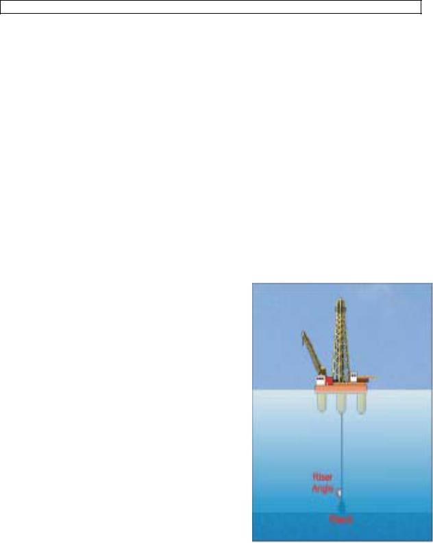
DRILLSHIPS
Drillships are directly involved with oil or gas exploration. Hence, if the drillship wanders off position to the extend that the connection to the well is severed, uncontrolled release of hydrocarbons could pollute and damage the environment. In addition, reconnecting to the well can be costly and time consuming.
Dynamic Positioning, usually class III system, is used to keep the drillship as directly above the well as possible.
Lower main riser angle is constantly monitored to ensure the vessel remains within3°. Water circles may be established to represent distances corresponding to riser angles.
A riser angle in excess of 3° is an indicationthat the drillship is drifting off location to the extend that the connection to the well may part.
Some DP systems on drillships have "riser angle mode" function to ensure that the
drillship is automatically maneuvered to reduce the riser angle.
CABLE LAY AND REPAIR VESSELS
Cable Lay and Repair Vessels have to load and lay fragile fiber-optic cables. Therefore, DP systems in these vessels enables them to have more control when handling cables.
DP also enables these vessels to maintain position and heading when they come to the end of the lay, usually close to the coast, to complete the shore-end tie-in connection. During this operation,

Dynamic Positioning System Capter7 OPERATIONS USING DYNAMIC POSITIONING
the water is often shallow with strong current.
PIPELAY VESSELS
Pipelay vessels have to maintain a constant tension in the pipeline during laying operation in order to prevent damage to the pipeline.
Pipeline tension data is automatically transmitted to the DP system.
The system then provide the necessary thrusters commands to enable the vessel to maintain tension.
In addition, these vessels have to lay the pipeline along an exact track. Hence, DP enables these vessels to follow the required track.
ROCKDUMPING AND DREDGING VESSELS
Vessels engaged in rock dumping are generally used to cover untrenched pipelines. DP systems in these vessels provide accurate track and speed control over the pipeline to be covered. Hence, the "auto-track" mode allows vessels to spread rocks evenly and economically.
Rockdumping vessels are also used to remedy erosion problems in some areas of the ocean. Vessels engaged in dredging operations range from clearing channels and harbors to recovering roadstones and building aggregates. DP systems in these vessels are used to ensure accuracy in dredging a defined area. The "auto-track mode" comes in handy for several dredging operations.
SHUTTLE TANKER AND FPSO VESSELS
A Floating Production, Storage, and Offtake units (FPSO) is generally a a turret moored tanker which weathervanes to maintain heading into the weather. FPSOs often use shutter tankers to transport the oil. As the FPSO wanders about her position, the shutter tanker has to maintain a relative position to prevent breaking the loading hose. Hence, the shutter uses DP for relative positioning off the FPSO.
OPERATIONS USING DYNAMIC POSITIONING
ACCOMMODATION AND FLOTEL UNITS
Accommodation and Flotel Units are generally barges used to support oilfield operations. These barges have to maintain position off other vessels or structures. Hence, DP is used when waterdepth, seabed activities, or other hazards render anchoring impossible.
CRANE BARGES AND CONSTRUCTION VESSELS
Crane Barges and Construction vessels are used in construction and de-commissioning operations in the oilfield. These vessel are also used in wreck recovery' or salvage work. Since these vessels have to operate relatively close to object (s) being lifted, they have to maintain position and heading to prevent collision. DP systems in these vessels are often more feasible
Dynamic Positioning System Capter7 OPERATIONS USING DYNAMIC POSITIONING
than anchoring.
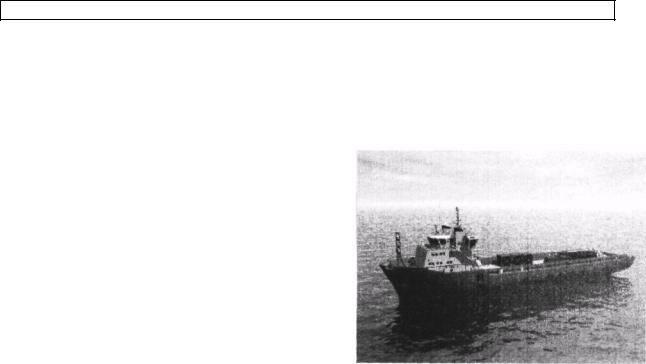
SUPPLYANDSTANDBYVESSELS
Supply and standby vessels usually come in lose proximity to oil rigs, platforms, barges, or other vessels for replenishment operations.
DP systems on these vessels enable them to stay on location a safe distance from obstructions. Hence, hazards associated with collisions are greatly reduced.
|
CRUISE AND PASSENGER VESSELS
Cruise and Passengers vessels are being built very large. However, the controlling depth of most channels remains the same. Consequently, these vessels are being designed with relatively shallow drafts for easy port access and large freeboards to accommodate more passengers. This raft/freeboard combination causes a challenge for maneuvering in restricted waters. Dynamic Positioning is used in these vessels to increase maneuverability.
OTHER VESSEL TYPES
Heavy-Lift Vessels - Vessels engaged in lifting heavy equipment, an oil platform for example, may wander off position when trying to lift or discharge cargo. DP systems enables these vessels to maintain position and heading when loading or discharging.
Military Operations - Some military vessels have DP systems installed to facilitate critical operations, for example, underway replenishment, mine countermeasures, etc.
DP OPERATIONS IN SHALLOW WATER
Dynamic Positioning in shallow water is degraded due to the following factors:
Strong currents in the vicinity of operation will cause the thrusters to work harder. Thereby, more power is consumed and the possibility of failure is increased. In addition, more noise is generated in the water.
The reduced distance between HPRs' transducers and transponders results in thrusters activities interfering with acoustic signals. Dynamic Positioning in shallow water is degraded due to these factors.
Tautwire system may become unreliable because of the shallow depth.
DP OPERATIONS IN VERY DEEP WATER

Dynamic Positioning System Capter7 OPERATIONS USING DYNAMIC POSITIONING
Dynamic Positioning in very deep water is complicated by the occasional presence of strong tides.
In addition, position references may become unreliable for the following reasons:
Taut wire system looses accuracy beyond depth of 300m. Even the taut wire system designed for depth down to 2000m, becomes inaccurate due to the angular resolution in very deep water. And, the wire tends to bend in strong tides.
Hydroacoustic Position References (HPR) loose reliability in very deep water because acoustic energy spreads with increased distance.
The Long Baseline systems (LBL) gives better accuracy in very deep water. 1 lowever, the refresh rate is relatively slow because sound travels in sea water at a rate of ! 500 m/s.