

A Savelyev DYNAMIC POSITIONING SYSTEM
.pdf
|
Dynamic Positioning System Chapter 3 |
PRACTICAL OPERATION OF A DP SYSTEM |
|
route
(track). For Low Speed Track Control, the speed of the vessel along the track is controlled very
accurately, in order to provide precise vessel movement along the leg. It is possible to add,
modify, or delete the route. There is a special waypoint table for every route, where waypoints
can be inserted, modified, or deleted as required. The following Heading functions are available:
Auto Heading:
Hold Heading - holds a current vessel heading when under Track Control. Set Heading - sets new heading and hold it automatically when under Track Control.
System Selected Heading - Track Control with heading directed to the next waypoint
at all times (BTW).
Manual Heading - manual heading control by knob rotation.
There are two possible strategies for Track Control Mode (Low Speed):
To slow down at every waypoint before movement towards the next one. This allows the
vessel to stay on a route (even in the case of large course changes).
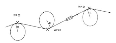
To pass a waypoint on a segment of the circle. DPO specifies the radius of the circle. The
same radius is used for all waypoints.
- 21 -
|
Dynamic Positioning System Chapter 3 |
PRACTICAL OPERATION OF A DP SYSTEM |
|
In the Track Control (Low Speed) Mode - DPO sets the following:
<> Set Vessel Speed - vessel speed value for movement under Track Control.
O Off Track Limit - DPO sets a distance (from the vessel to a track) within which the vessel can move on either side of the track. When this limit is exceeded, the system gives an alarm.
O Track Gain - DPO an operator sets Track Control Controller sensitivity.
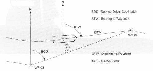
The following information is displayed under Track Control:
XTE
DTW
BOD
BTW
TRACK CONTROL INFORMATION
NOTE: When the Track Control mode is switched on, the vessel moves to the nearest leg of the route and then, follows the next one.
The Track Control Mode (Low Speed) can be started if the distance between the vessel and the nearest leg of the route is less than 300 feet.
The operator may select either Manual Heading or Auto Heading in all Joystick and DP modes.
The table on the following page contains the full list of system modes.
- 22 -
|
Dynamic Positioning System Chapter 3 |
PRACTICAL OPERATION OF A DP SYSTEM |
|
MODE |
|
CONFIGURATION |
|
|
|
|
|
|
|
|
|
|
|
JOYSTICK MODE |
|
|
|
|
|
|
|
|
|
|
|
||
|
|
Manual Position (MP) & Manual Heading (MH) |
||||
|
|
Manual Position & Auto Heading (AH) |
|
|||
|
|
|
|
|
|
|
DP MODE |
|
|
|
|
|
|
|
|
|
|
|
|
|
Semi- |
|
Manual Surge / |
|
Auto Surge / |
|
Manual Speed |
|
Auto Sway |
|
Manual Sway |
|
Vector |
|
Automatic |
|
|
||||
|
|
|
|
|
||
MSurge & MH |
|
Msway & MH |
|
MSpeed & MH |
||
|
|
|
|
|||
|
|
MSurge & AH |
|
Msway & AH |
|
MSpeed & AH |
|
|
|
|
|
|
|
Auto- |
|
Auto Position & Manual Heading |
|
|||
Positioning |
|
|||||
Auto Position & Auto Heading |
|
|||||
|
|
|
||||
|
|
|
|
|
|
|
ROV Following |
ROV Following & Manual Heading |
|
||||
|
|
|
||||
|
|
ROV Following & Auto Heading |
|
|||
|
|
ROV Following & System Selected Heading |
|
|||
Track |
Control |
Low Speed Tracking & Manual Heading |
|
|||
(Low Speed) |
|
|||||
Low Speed Tracking & Auto Heading |
|
|||||
|
|
|
||||
|
|
Low Speed Tracking & System Selected Heading |
||||
|
|
|
|
|
|
|
AUTOPILOT MODE |
|
|
|
|||
|
|
|
|
|||
|
|
Manual Course Keeping |
|
|||
|
|
Auto Course Keeping |
|
|||
|
|
Track Control (High Speed) |
|
|||
|
|
|
|
|
|
|
- 23 -
|
Dynamic Positioning System Chapter 3 |
PRACTICAL OPERATION OF A DP SYSTEM |
|
AUTOPILOT CONTROL MODE
Used for heading control when underway moving ahead. Propellers are working synchronously.
The DPO, using the Engine Telegraph, provides vessel speed control manually. The synchronized rudders provide heading control. The following modes are available:
Manual Course Keeping - direct manual control of synchronized rudders, using the rotary knob. Auto Course Keeping - automatic heading holding.
The following functions are included:
Hold Heading – holds present course.
Set Heading – sets a new course and steer to it automatically.
TRACK CONTROL (HIGH SPEED)
The vessel travels along the connecting line (leg) between two waypoints from the selected route (track).
High Speed Track Control - DPO using the Engine Telegraph controls the speed of the vessel along the track manually. Vessel Heading is controlled by the IVCS (using synchronized rudders). In this mode, the vessel is always moving forward to the next waypoint.
It is possible to add, modify, or delete the route. There is a special waypoint table for every route, where waypoints can be inserted, modified, or deleted as required.
The following illustrates a vessel movement in the Track Control (High Speed) Mode. When passing a waypoint, the vessel moves on a segment of the circle. DPO specifies the radius of the circle. The same radius is used for all waypoints.
In the Track Control (High Speed) Mode - DPO sets the following: Set Turn Radius - radius of a turning circle.
Off Track Limit - the operator can set a distance (from the vessel to a track) within which the vessel can move on either side of the track. When this limit is exceeded, the system gives an alarm.
- 24 -
|
Dynamic Positioning System Chapter 3 |
PRACTICAL OPERATION OF A DP SYSTEM |
|
Track Gain - an operator sets Track Control Controller sensitivity.
The following information is displayed under Track Control:
XTE
DTW
BOD
BTW
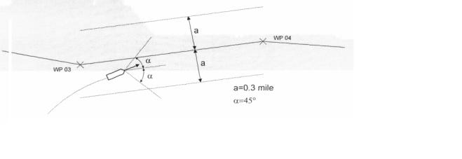
The Track Control Mode (High Speed) can be started if the distance between the vessel and the nearest leg of the route is less than 0.3 mile and difference between the vessel heading and BOD is not more than 45°.
TRACK CONTROL (HIGH SPEED) MODE STARTING CONDITIONS
NOTE: When the Track Control mode is switched on, the vessel moves to the nearest leg of the route and then, follows the next one.
- 25 -
Dynamic Positioning System Chapter 3 |
PRACTICAL OPERATION OF A DP SYSTEM |
CONTROLS AND INDICATORS
Each of two Operator Consoles consists of an LCD display with touch screen, Main Control Panel, and Alarm Speaker.
All computers, PLCs, power supplies, interconnecting LAN data, busses and sensors are duplicated by redundant circuits. Both systems are identical and either one may be selected as "Master" and the active console at start-up.
When the "Master" console is active it controls the vessel. The "Hot Standby" console is passive and it displays all actions of the "Master" console only. It is possible to transfer control from the "Master" to the "Hot Standby" system at any moment. At this time, the "Hot Standby" system becomes the "Master" and vice versa.
One Operator Console is Forward Facing and another is Aft Facing. All descriptions and figures in this Manual are for Forward Facing Console ("Master").
POWER PUSHBUTTON
Used for switching system power On/Off. The button is illuminated when the power is on. To switch power off, it is necessary to hold this button for 2 seconds, after which the Computer will be shut down. Then, the LCD and Touch Screen power and Control Panels power is switched off immediately and all other system components will automatically be switched off in 3 (three) minutes.
The "Power" pushbutton is equipped with a green LED Indicator, which is illuminated when the Computer is connected and is an indicator of Control Panel and Computer operation.
NOTE: Each Operator Console (A and B) should be switched On/Off separately.
STEERING SELECTOR
The Steering Selector is the main switch, which allows the IVCS 2000 to accept control. It is not a part of the IVCS 2000 system and it is located on the Steering Console. There are two positions of the Steering Selector:
Bridge - Vessel Control from Bridge Control Station.
DP - Vessel Control from the IVCS 2000 ("Master" console).
“BRIDGE” MODE INDICATORS
The red “Bridge” LED Indicator is illuminated, when the IVCS 2000 is in the Bridge Mode, i.e. Vessel Control is provided from the Bridge Station when the Steering Selector is in the “Bridge” position. When the IVCS 2000 (DP) controls the Vessel, the “Bridge” LED indicator is not illuminated.
MANUAL PROPULSION CONTROLS
- 1 -
Dynamic Positioning System Chapter 3 |
PRACTICAL OPERATION OF A DP SYSTEM |
Heading Control Knob - This is the stay-put Rotary Control Knob with center detent, which directly controls the proportional heading control moment when Manual Heading Mode is selected. When the Autopilot Mode is selected, the Control Knob is used to control rudder angle.
Position Control Actuator (Joystick) - This is two-axis stay-put Joystick used in Manual Position Mode, for selecting thrust levels for the fore-aft and athwartships axis. Force level is proportional to the deflection in each axis.
It is also possible to control the Vessel Speed vector by Joystick in the Manual Speed Vector Mode. Matching Indicators - These are intended to indicate the Joystick and/or Rotary Knob
adjustment necessary to maintain the current DP thrust when changing to manual from automatic position keeping. It eliminates the unwanted jump in positioning control, which would otherwise occur.
CONTROL TRANSFER PUSHBUTTON AND INDICATOR
The “Accept Control” Pushbutton is assigned for Control transfer between “Master” console and “Hot Standby” console and between Main Control Panel and Portable Control Panel of the “Master” Console. A green LED Indicator in the “Accept Control” Pushbutton indicates that console is in control. When first switching the IVCS 2000 on, the Main Control panel of the “Master” console becomes active.
To start Control Transfer Procedure between “Master” and “Hot Standby”, press the “Accept Control” button on the Operator Console, where control is to be transferred to, and hold it for two seconds. Control is then transferred to this console, its LED indicator becomes illuminated and that on the previous console becomes extinguished.
The procedure to start Control Transfer Procedure between Main Control and Portable Control Panels of the “Master” Console is the same as described above. NOTE: If the Portable CP is connected to the “Hot Standby” Main CP, the Control Transfer Procedure is the same.
The “Accept Control” Touchscreen Control Button on the display serves the same function.
Enter Pushbutton – This is used to acknowledge the Touchscreen button requests. The button on the top of Joystick lever and the “Enter” Touchscreen Control Button on the display serve the same function.
Alarm Acknowledge - This is used to acknowledge new alarm conditions as displayed in the alarm window (and on last alarm/message line) of the led.
Lamp Intensity - There are two buttons “dimmer +/-” on the control panel, which are used for increasing/decreasing panel illumination. for lamp test, press both these buttons, simultaneously.
Hold Heading Pushbutton And Indicator - the “hold hdg” pushbutton and indicator can be operated only in the j/dp and auto pilot modes and is used to lock in the present heading for automatic course control. A momentary press will engage, the led indicator goes out, and the system passes to the manual heading mode. To take manual control, it will be necessary to synchronize the heading knob with its led indicators.
HOLD POSITION PUSHBUTTON AND INDICATOR
The “Hold POS” Pushbutton and Indicator can be used only in the J/DP Mode and is used to select the Auto Position Mode. When pressed momentarily, the actual vessel’s position is locked in for automatic position holding. When held down steady, the LED indicator goes out and the system
- 2 -
Dynamic Positioning System Chapter 3 |
PRACTICAL OPERATION OF A DP SYSTEM |
passes to the Manual Position Mode. To take manual control, it will be necessary to synchronize the Joystick with its LED indicators.
CENTER OF ROTATION PUSHBUTTON AND INDICATOR
Press the “Remote COR” button to transfer Center of Rotation from center of gravity to stern or to bow, depending on settings made in the Parameters Window (Joystick section). This function can be used only when the Manual Heading Mode is activated.
AUDIO VOLUME
The Audio Volume Knob is used for volume control of voice alarms on the external loud speaker.
CONTROL FROM LCD WITH TOUCH SCREEN
After switching power on and the system has self-loaded and the Main Screen appears on the LCD, DPO can choose one of the following options by touching the display at the desired Mode:
Real Mode. Starts the IVCS 2000 operation in Real Mode.
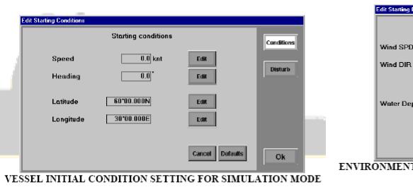
Simulator Mode. Starts the IVCS 2000 in Simulator Mode. Before this mode is started, it is necessary to set the initial conditions (using a Numeric keypad) in the window for vessel and environment conditions. Then, press “OK” Softkey to load the IVCS 2000 in the Simulator
Mode.
Services. This mode allows the service engineer to monitor the system operation, using the following submodes:
Monitor – Runs the special “Monitor” Utility, which can be used for monitoring of data exchange between the IVCS 2000 and PLCs.
PLC Faults – Runs the special utility, which monitors PLC failures. Alarm Viewer – Runs the Alarm Viewer.
COM Ports – Runs the special utility, which monitors the raw data.
Shut Down. Choose this option to start the Computer Shut Down procedure. After that, hold the “Power” button on the Main Control panel for 2 seconds and the power will automatically be switched off in 3 minutes.
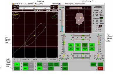
DISPLAY AREA STRUCTURE
The display is divided into 5 fixed areas:
- 3 -
Dynamic Positioning System Chapter 3 |
PRACTICAL OPERATION OF A DP SYSTEM |
Status Line. This field contains the selected mode title, date, and time.
Alarm/Message Line. The last current not acknowledged (or last not acknowledged). alarm message from the J/DP System is indicated in this field.
Mode/Function Control Buttons area. Selected buttons are illuminated green. Left Operator Selected Page.
Right Operator Selected Page.
The following Operator Selected Pages are provided in the IVCS 2000: Hold Plot & Auto Thrusters. Position &
Heading Display. Alarms.
Sensors.
Reference Systems. Parameter Manual
ThrustersSelect Rout Track Control. ROV position. Capability Diagram. System Monitor.Power Mo Autopilot.
The following additional windows can appear in front of the display upon pressing certain buttons (e.g. “Auto HDG”, “Auto POS”, “Select Windows”, etc.):
Data Input Windows. Select Window.
More detailed description of display areas and windows follows:
STATUS LINE
The middle part of the line contains messages about the selected mode of system operation: Bridge Control.
Simulator Mode.
Vessel name is displayed in the right part of the Status Line.
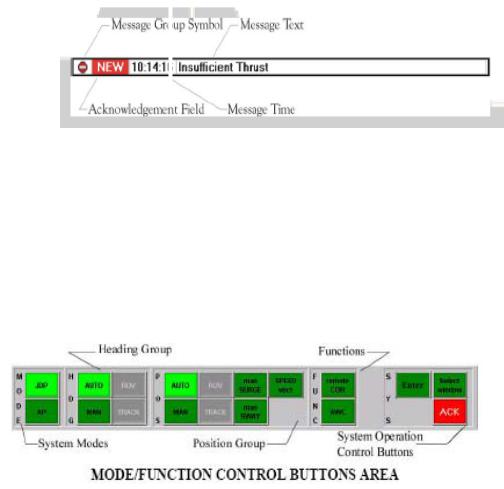
ALARM/MESSAGE LINE
The following information is located in this line (from left to right):
O The symbol, defining message group (Error, Warning, Information). O Field of message acknowledgement.
'O Time stamp. O Message text.
- 4 -
Dynamic Positioning System Chapter 3 |
PRACTICAL OPERATION OF A DP SYSTEM |
LAST
ALARM / MESSAGE LINE
MODE/FUNCTION CONTROL BUTTONS AREA
The Main Softkeys are located in this area.
Active Main Softkeys are green and can be pressed. Passive Main Softkeys are grey. Structure of active Softkeys is defined by chosen mode.
After pressing a Main Softkey, it blinks. Press the "ENTER" Pushbutton on the Control Panel or Joystick Pushbutton to acknowledge (then the button becomes bright green), press any active Main Softkey for cancellation (or press the "Cancel" button in the additional window).
Button Groups:
MODE Group - the IVCS 2000 mode selection. Only one button can be pressed at the same time.
JDP - J/DP mode On/Off. AP - Autopilot mode On/Off.
HDG Group - Heading Control mode switching. Only one button can be pressed at the same time.
MAN - J/DP Manual Heading Control and AP Manual Course Keeping modes On. AUTO - J/DP Auto Heading Control and AP Auto Course Keeping modes On. TRACK - AP Track Control (High Speed) mode On / System Selected Heading
submode of the Track Control (low Speed) Mode.
ROV - System Selected Heading submode of the ROV Follow Mode (ROV following with heading directed to the moving target at every moment).
POS Group - J/DP Position Control mode selection. Only one button can be pressed on the same time.
MAN - J/DP Manual Position Control mode On. AUTO - J/DP Auto Position Control mode On.
- 5 -