

A Savelyev DYNAMIC POSITIONING SYSTEM
.pdfDynamic Positioning System Chapter 3 |
PRACTICAL OPERATION OF A DP SYSTEM |
This parameters group is used for setting proper date, time and time zone.
System Settings Window contains the following settings:
^System Date. This is a parameter for setting date (in month-day-year format).
^System Time. This is a parameter for setting time.
Q> Time Zone. This parameter is intended setting time zone.
GENERATOR LIMITS
In this window, an operator can set low and high voltage and frequency limits for generators. When these limits are overstepped, an alarm appears.
Using "<" and ">" buttons it is possible to set required limit values for the following generators:
^Port Generator.
^Stbd Generator.
Generator limits cannot exceed maximum voltage and frequency values, defined by generators' specifications.
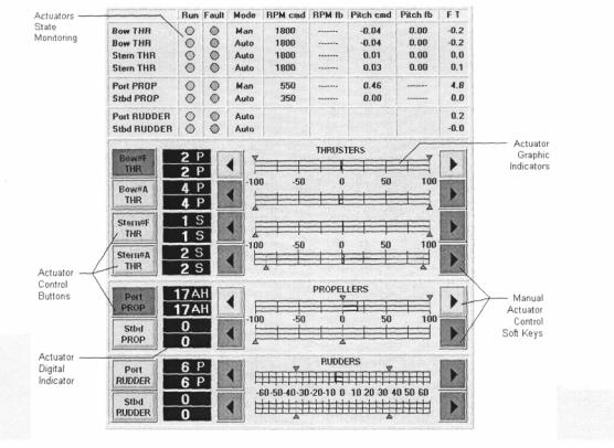
MANUAL THRUSTER WINDOW
This window is used:
O For Actuators state monitoring (upper part).
O For manual control of the actuators in the Stand By Mode (lower part).
O For manual control of actuators, which are disconnected from automatic control, in J/DP Mode (lower part).
It is also possible to switch on/off actuators in Auto Mode.
There are two areas in this window:
O Actuators state monitoring (upper part) indicates the following state data (for every vessel actuator):
t* Run indicator - colored circle indicator of Engine Run signal, the color indicates status:
•Green - actuator is started and ready for operation.
•Red — actuator is not ready for operation.
•Grey - actuator Engine Run signal is not present for this vessel. t> Fault indicator - colored circle indicator shows:
•Red color — actuator is failed.
•Grey color - actuator is operable correctly.
&> Mode - actuator operating mode:
•IVCS 2000 Auto.
•IVCS 2000 Manual.
•Bridge mode.
&» Actuator RPM command (if available). I*- Actuator RPM feedback (if available). If Actuator Pitch command (if available). t* Actuator Pitch feedback (if available). &» Force (T) - actuator thrust (ton).
O Actuators control part (lower) allows an operator to switch on/off actuators in Auto Mode
- 16 -
Dynamic Positioning System Chapter 3 |
PRACTICAL OPERATION OF A DP SYSTEM |
and manually control actuators in the Stand By Mode and actuators, which are disconnected from automatic control, in J/DP Mode. The following buttons and indicators for each Actuator are located in this part of the Manual Thruster Window:
P> Softkey for switching Actuator on/off into Auto Mode operation (Actuator Control Buttons), analogous.
9» Digital indicator Actuator Set Value (white).
|
MANUAL THRUSTER WINDOW |
|
|
|
|
&» |
Digital indicator Actuator Actual Value (yellow). |
|
|
|
|
> |
Softkeys for Manual Actuator Control (^^-). Light green |
color |
of |
the |
button |
|
indicates that the Actuator is disconnected from the Auto Mode and it is possible to |
||||
|
control it manually. Dark green button colour indicates that the button is passive, |
||||
|
because the Actuator is used for control in Auto Mode. ^ |
- Actuator |
Set |
Value |
|
|
increase and -^ - Actuator Set Value decrease. For slow adjustment on a unit, press a |
||||
|
Softkey once. For fast changes, hold the button down continually until the desired |
||||
|
adjustment is achieved. |
|
|
|
|
I* |
Actuator Graphic Indicator After switching off an Actuator, its |
setting |
is saved |
and it |
|
|
can be changed later by the Manual Actuator Control buttons. |
|
|
|
|
- 17 -
Dynamic Positioning System Chapter 3 |
PRACTICAL OPERATION OF A DP SYSTEM |
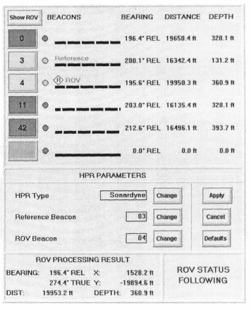
ROV FOLLOW WINDOW
This window is used for:
O Raw data monitoring from active beacons.
O Beacon selection for ROV Following.
O Reference beacon selection for determining vessel position.
^Acoustic(HPR) type selection.
^ROV Processing Results monitoring.
The window is divided into four areas.
O Raw data from beacons: &* Bearing (true or relative). l> Distance to beacon.
> Depth (from beacon to ground).
For Distance and Depth units are set in accordance with position display settings.
Active beacon buttons are dark
green. An operator can set one of the active beacons as an ROV or as Reference by
pressing the respective "Change" button in the "HPR Parameters" section of the window. Press the "Apply" button in the "HPR Parameters" section to acknowledge. At that
moment, the selected button changes to bright green, the X?- ROV symbol appears over the "Beacon Data Trend Monitoring" indicator, the ROV symbol appears on the Motion Plot instead of the respective beacon symbol, the "ROV" Main Softkey and the "ROV" button in the Heading Setpoint Editor become active.
There are graphical indicators for "Beacon Data Trend Monitoring", which indicate the following possible situations:
t> Beacon is not active - white zone. fe> No beacon data - black zone. 6» Valid beacon data - green zone. l> Invalid beacon data - red zone.
The button in the upper left corner of this section selects display of all active beacons or only ROV beacon on the Motion Plot.
- 18 -
Dynamic Positioning System Chapter 3 |
PRACTICAL OPERATION OF A DP SYSTEM |
|
0 H PR Parameters |
|
|
I* |
HPR Type - press the respective "Change" button to switch between "Sonardyne", |
|
fr1 |
"Simrad" and "ATS II Nautronix" hydro-acoustics. |
|
Reference Beacon. |
|
|
1> ROV Beacon.
One of the active beacons can be set as ROV or as Reference by pressing the respective "Change" button. Press the "Apply" button to acknowledge.
NOTE: ROV Beacon cannot be changed in the ROV Following Mode. HPR Type and Reference beacon can be changed only when HPR Sensor in the Reference Systems Window is disabled.
^ ROV Processing Results
t» Bearing (true or relative). 8> Distance to ROV.
&• Depth (from ROV to ground).
l> X and Y ROV coordinates (earth reference).
O^ ROV Following Status
I* Pause - ROV Following Mode is switched on and ROV following is paused. l> Following - The vessel is following the ROV.
> Not active - ROV Following Mode is switched off.
SELECT ROUTE WINDOW
This window is used for preparing the system for operation in the Track Control (Low Speed/High Speed) Modes. It allows an operator to carry out the following operations:
O- Route List Editing.
& Set Active Route.
<>• Editing of Waypoint List for every route, route name, and Status.
The window is divided into two areas.
& Route List (upper part). - This part contains list of routes, where route name and status (H for High Speed and L for Low Speed) are indicated.
NOTE: If the Select Route window is active, then a graphic presentation (polyline) of the
current route from the Route List |
appears on the Motion Plot. Upon closing the Select |
Route Window, all route polylines |
disappear from the Motion Plot except of the Active |
route representation (see below). |
|
- 19 -

Dynamic Positioning System Chapter 3 |
PRACTICAL OPERATION OF A DP SYSTEM |
|||||
The following control buttons |
|
|
||||
are located from the right of the |
|
|
||||
Route List: |
|
|
|
|
|
|
S» |
t and •I' Softkeys -- for |
|
|
|||
|
route selection. |
|
|
|
|
|
^ |
Set |
Active |
- |
press |
this |
|
|
button |
to |
set |
the |
current |
|
|
route as Active route. |
|
|
|||
|
The selected route row |
|
|
|||
|
color is changed to dark |
|
|
|||
|
red. |
|
|
|
|
|
|
Graphic presentation of |
|
|
|||
|
the |
selected |
route |
|
|
|
|
appears on the Motion |
|
|
|||
|
Plot (dark red polyline) |
|
|
|||
|
and |
remains |
there |
|
|
|
|
during all the time of |
|
|
|||
|
route active status. |
|
|
|||
|
Way point list of the |
|
|
|||
|
selected Active |
route |
|
|
||
|
appears in the Track |
|
|
|||
|
Control Window. |
|
|
|||
|
The |
Track |
Main |
|
|
|
|
Softkey becomes active |
|
|
|||
|
depending |
of |
route |
|
|
|
|
status (for Low Speed |
|
|
|||
tracking the Track Main Softkey becomes active when the system is in the J/DP
Mode, for High Speed Tracking - when the system is in the Autopilot Mode). To cancel Active route, select it and press the Set Active softkey.
To set another route as Active, select route and press the Set Active Softkey.
NOTE: It is prohibited to change active route when the IVCS 2000 is operated in the Track Control (Low Sped / High Speed) Modes.
^ Add Route - press this button to add a new route into the list. A row with new route appears above the current route.
&» Edit Route - softkey is used for current route editing. Upon pressing this button, the lower part of the Select Route Window becomes active.
te» Del Route - deleting the current route from the list.
Route particulars (lower part of the window) - This part is used for current route particulars indication and editing. It shows the waypoint list of selected route (number and coordinates of WP), route name, and status. The following control buttons are located in this part of the Select Route window:
>Route Name - upon pressing this button the Rote name Editor appears, allowing editing name of the route.
i> Set Status - use this button to change status of the selected Route.
NOTE: It is prohibited to change status of active route when the IVCS 2000 is operated in the Track Control (Low Sped / High Speed) Modes.
T and •!• Softkeys - for way point selection.
Add Point. Press this button to add a new waypoint into the WP list. NOTE - that
- 20 -
Dynamic Positioning System Chapter 3 |
PRACTICAL OPERATION OF A DP SYSTEM |
a row with new waypoint appears above the current waypoint route.
Edit Point Softkey is used for current WP editing. Upon pressing this button, the Waypoint editor appears where an operator can input WP coordinates.
Del Route - deleting the current waypoint from the list. OK and Cancel - acknowledge buttons.
NOTE: Control buttons of the lower part of the screen become active only after pressing the Edit Route control button, in the upper part of the window.
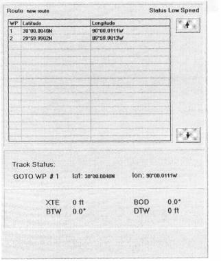
TRACK CONTROL WINDOW
This window is used for the IVCS 2000 Track Control (Low Speed / High Speed) Modes monitoring. The window is divided into two areas:
^ The upper part displays Active Route characteristics:
b* Route name. & Route Status.
fc» Waypoint List of Active Route. & Row with a GOTO waypoint is
marked out.
P- Use the t and •!• Softkeys to look
through the list.
NOTE: All data appears in the upper
part of the Track Control window only after Active Route setting.
The following Track Control data is indicated in the lower part of the window: 0* Track Status (only for Low Speed Tracking):
B> Pause - Track Control (Low Speed) Mode is switched on and tracking is paused. &> Following - The vessel is following along a route.
l> Not active - Track Control (Low Speed) Mode is switched off. fe» Number and Lat. Lon. coordinates of the GOTO waypoint, &• Tracking data: XTE, BOD, BTW, DTW.
6» Track Control strategy: Stop/Non stop (only for Low Speed Tracking).
Note: All data appears in the lower part of the Track Control window only after loading Track Control (Low Speed / High Speed) Mode.
- 21 -
Dynamic Positioning System Chapter 3 |
PRACTICAL OPERATION OF A DP SYSTEM |
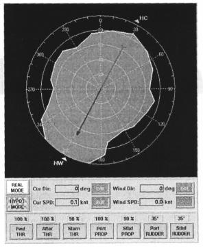
CAPABILITY DIAGRAM
This window contains results of the IVCS 2000
Capability Analysis and allows an operator to set
different system configuration and select environmental conditions to forecast the maximum weather conditions, in which the vessel can maintain position and heading.
By examining this window, an operator can clearly see the current (or forecasted) operational
limits for current (or set) environmental conditions and select an optimal heading for most safe operations.
There are two modes of the Capability
Diagram
Window operation:
&Real Mode - In this mode, the system indicates the maximum weather conditions in which the vessel is able to
continue DP operation for current system configuration (thrusters set and maximum loading), actual current
conditions (speed and direction), and actual wind direction. To operate the Capability
Diagram Window in the Real Mode, press the Real Mode control button in the middle part of the window.
^ Hypothetic Mode - Forecast of the maximum weather conditions for which the vessel can maintain position and heading for set system configuration (thrusters set and maximum loading), set current conditions (speed and direction) and set wind direction. To operate
the Capability Diagram Window in the Hypothetic Mode, press the Hypot Mode control button in the middle part of the window.
The Capability Diagram Window has the following structure:
^ The upper part of the window contains the Capability Plot, where the following information is indicated:
6> Circle Grid, where each of concentric circles points a wind speed value and rays determine relative vessel heading direction.
I"" Blue-red arrow points North direction.
b» Wind direction (actual for Real Mode and set for Hypothetic Mode) - yellow triangle with symbols HW.
&* Current direction (actual for Real Mode and set for Hypothetic Mode) - green
- 22 -
Dynamic Positioning System Chapter 3 |
PRACTICAL OPERATION OF A DP SYSTEM |
triangle with symbols HC.
^Area, within which the vessel can maintain position and heading depending on wind speed.
^This area is determined by the actual current speed and direction and the actual wind direction for the Real Mode and by set current speed and direction and set wind
direction for the Hypothetic Mode.
O1 The middle part of the window is used for:
t^ Operational Mode selection: the Real Mode and the Hypot Mode control buttons. The following values indication for the Real Mode and setting for the Hypothetical Mode: True current speed.
True current direction.
True wind speed (can not be edited in the Hypothetic Mode.) True wind direction.
&> To edit wind and current settings in the Hypothetic Mode, press the Edit softkey.
Special editors appear, where an operator can set desirable values.
O1 The lower part of the Capability Diagram window is used for monitoring (for the Real Mode) and setting (for the Hypothetic Mode) thrusters configuration and maximum loading (actuator limits) and contains the following:
^Indicators of Auto or Manual actuator using in the IVCS 2000.
I*" Indicators of actuator limits.
To modify actuators set or actuator limits in the Hypothetic Mode, press an actuator control button. A special editor appears, where an operator can set desirable value of actuator (using a Numeric keypad) and switch on/off an actuator on/off into Auto Mode operation.
SYSTEMS MAIN FUNCTIONS
ACTIVE WIND COMPENSATION
Control forces and moments are generated to compensate for wind disturbance. It is possible to use this function in all J/DP modes. In AWC, a "Mode Feed Forward Controller" works independently of the selected J/DP mode, countering the wind disturbance before it can move the vessel.
REMOTE CENTER OF ROTATION
This function can be used only when the Manual Heading Mode is activated. DPO can choose center of gravity, bow, or stern as the center of rotation.
THRUST ALLOCATION
DPO can set any desirable combination of propellers, rudders, and thruster, and also can choose the desired thrust allocation algorithm.
THRUST ALLOCATION FUNCTION
Used only in J/DP mode. At any given moment the fore-aft and athwartships forces and rotary
- 23 -
Dynamic Positioning System Chapter 3 |
PRACTICAL OPERATION OF A DP SYSTEM |
moment, which are necessary for vessel position and heading control, are calculated. The required forces and moment are provided by the thrust of propellers, rudders, and thruster. The turning angle and/or thrust of the various actuators are controlled to provide the necessary forces.
If the thrust of propellers, rudders, and thruster is not enough for provision of the required forces and moment, the Thrust Allocation function gives a priority to the generation of rotary moment.
ACTUATOR LIMITS
It is possible to set control limits for every rudder, propeller, and thruster in vessel configurations: rudder angle deflection limits and propeller RPM limits.
ACTUATOR CONFIGURATION
Upon connection/disconnection of one or several propellers, rudders, or thruster from the system or upon them being manually controlled by the operator, the Thrust Allocation function will automatically redistribute thrusts for the new actuator configuration.
CONSEQUENCE ANALYSIS SYSTEM
The following functions are included in the IVCS 2000 Capability Analysis System:
O Indication of the maximum weather conditions in which the vessel is able to continue DP operation for current system configuration (thrusters set and maximum loading), actual current conditions (speed and direction), and actual wind direction.
O Forecasts of the maximum weather conditions for which the vessel can maintain position and heading for set system configuration (thrusters set and maximum loading), set current conditions (speed and direction), and set wind direction.
The weather conditions are determined by a one-minute mean maximum wind speed.The result of the analysis is displayed graphically as a polar plot.
- 24 -
Dynamic Positioning System Chapter 4 |
POSITION MEASUREMENT EQUIPMENT |
POSITION MEASUREMENT EQUIPMENT
Position accuracy, reliability, and consistency are critical for DP operation. Therefore, the most important concern of the DPO is maintaining adequate and reliable position measurement equipment.
The number of position measurement equipment used will depend upon a many factors, especially the level of risk involved in the operation, the 1MO Equipment Class in force for that operation, the availability of references of a suitable type, and the consequences of loss of one or more position references.
Five types of Position Measurement Equipments (PMEs) are generally used on DP vessels, operating separately and independently of the DP system, and using an interface to feed information to the DP:
-Hydroacoustic Position Reference (HPR).
-Artemis.
-Taut Wire.
-Differential Global Positioning System (DGPS). -Laser-based systems.
Normally, the DP system can handle multiple PME input by pooling the information to provide a continuous "best fit" of position data. This process is a function of the mathematical modeling of the system.
HYDROACOUSTIC POSITION REFERENCE (HPR)
Acoustic energy propagates underwater at a much higher efficiency than in air. Acoustic energy has been developed over many years and has been applied to DP position reference. HPR uses underwater acoustics to determine position and track ROB, equipment, and more. A variety of alternative acoustic position measurement equipments are used. Most of them are based upon the range measurement possible, related to the time travel of acoustic signals underwater. Three types of HPRs are generally used:
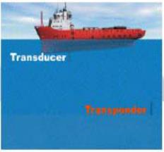
ULTRA OR SUPER-SHORT BASELINE SYSTEM (USBL OR SSBL)
The most commonly used HPR for DP position reference purposes.
A transducer, mounted in the hull of the DP vessel, transmits an interrogating pulse.
This pulse automatically activates
one or more transponders positioned on the seabed. And, a reply is transmitted.
The transponder receives the reply. And, the time difference between transmission and reception is used to compute the range and angle at the transducer head (short baseline).
Thus, the DP vessel's position relative 10 me iranspunucr is ueicnnmeu.
In the USBL system, the acoustic transmit and receive elements are combined into one hullmounted transducer. This communicates at acoustic frequencies with one (or more) subsea transponders, in order to provide positioning. In its basic configuration, the system consists of a control and display unit, a transceiver unit, a transducer unit mounted on the end of a probe in the
- 1 -