

A Savelyev DYNAMIC POSITIONING SYSTEM
.pdfDynamic Positioning System Chapter 3 |
PRACTICAL OPERATION OF A DP SYSTEM |
ROV - Remote Operated Vehicle Following mode On. TRACK - J/DP Track Control (Low Speed) mode On.
Speed Vector - J/DP Semi-Automatic Position mode Manual Speed Vector submode On.
Man Surge - J/DP Semi-Automatic Position mode Manual Surge & Auto Sway submode On.
Man Sway - J/DP Semi-Automatic Position mode Auto Surge & Manual Sway On. O FUNC Group - the IVCS 2000 functions On/Off. Several buttons can be pressed at the
same time.
Remote COR - Set Remote Centre Of Rotation. AWC - Active Wind Compensation.
SYS - the IVCS 2000 operation control buttons.
Select Window - setting of Left/Right Operator Selected Pages.
ACK - Alarm Acknowledge Button. Press this button to acknowledge an alarm displayed in the Last Alarm / Message Line.
Enter - acknowledgement of a softkey pressing.
ADDITIONAL WINDOWS
DATA INPUT WINDOWS
Data Iput windows are used for parameter values entering and basically have the following structure:
Indicators. Editing Fields.
Numeric |
Keypad - the Numeric |
||
keypad |
consis |
of: |
|
|
|
Digital softkeys. |
|
|
“Left |
Arrow” |
and |
|
“Right |
Arrow” |
– |
|
Choice of edited field. |
||
|
“+/-“ – Set direction |
||
|
(e.g. North – South). |
||
|
OK |
|
– |
|
Acknowledgement |
of |
|
entered value(s) and closing of Data Input Windows. Cancel.
Alpha-Numeric Keypad – The Alpha – numeric keypad is used for entering both letters and digits. It consists of:
Alphabetical/Digital Softkeys.
“Left Arrow” and “Right Arrow” – Choice of adited field. "Num/ABC" switcher.
"Space" Softkey.
"Delete" Softkey.
OK - Acknowledgement of entered value(s) and closing of Data Input Window.
- 6 -
Dynamic Positioning System Chapter 3 |
PRACTICAL OPERATION OF A DP SYSTEM |
Cancel.
NOTE: To enter a letter, you should press a corresponding softkey once, twice or three times, depending on the letter location on the softkey. For example, to enter the "b" letter, press the softkey twice.
The following Data Input Windows could be displayed:
0 Heading Setpoint Editor - appears upon pressing the "Auto HDG" Main Soft Key or at heading settings in the Parameters Window. It consists of the numeric keypad and the following indicators:
> Hold Button. Press this button to put Actual Heading into the Editing Field.
l> Offset Button - New Heading Setpoint input as offset of Actual Heading value. Upon pressing the Offset Button, value of Editing Field become zero, after which the Heading Setpoint offset can be set.
I* Min Pwr. Press this button to display an automatically calculated "Min Power" Heading value in the Heading Editing Field. Press the "OK" softkey to automatically hold calculated Heading value.
0 Position Setpoint Editor - appears upon pressing the "Auto POS" Main Soft Key or at Position settings in Parameters Window. It has the numeric keypad and the following indicators structure:
fr1 Latitude Editing Field. ^ Longitude Editing Field.
&* Hold Button - Press this button to put Actual Vessel Lat. and Long, into the Editing
Fields.
&» Offset Button - New Position Setpoint input as offset of Actual Position Setpoint. Upon pressing the Offset Button, values of both Editing Fields become zero, after which, the Position Setpoint offset can be set. Offset value and direction are
determined by:
Position Display View Mode:
•Lat. and Long, offsets for True Mode (North - South and West - East).
•Surge and Sway offsets for the relative mode (Forward - Astern and PORT - STBD).
•Set Units (see View Settings).
•Meters.
•Feet.
•Cables.
l> Position Setpoint Offset function is not provided for Lat./Long. Units .
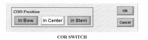
l> COR Switch - Press Main Softkey "remote COR" for the COR Selection Window to appear.
COR Selection Window has the following button structure:
COR Position Buttons for setting Center of Rotation:
•In Bow.
- 7 -
Dynamic Positioning System Chapter 3 |
PRACTICAL OPERATION OF A DP SYSTEM |
•In Center (gravity center).
•In Stern.
•The set COR is indicated by white color.
OK - Acknowledgement of set COR and closing of COR Selection. Cancel.
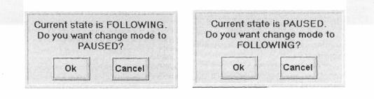
*• ROV Active - Press the "ROV" Main Softkey in the POS Group for the ROV Active Window to appear. Using this window the DPO can pause/proceed ROV Following at any moment.
ROV MODE SWITCH
^Track Control (Low Speed) Active - Press the "TRACK" Main Softkey in the POS Group for the Track Control (Low Speed) Active Window to appear. It has the same structure as the "ROV Active" Window. Using this window the operator can stop/proceed Track Control (Low Speed) at any moment.
^Route Name Editor - appears upon pressing of the "Route Name" Softkey in the Select
Route Window. It consists of the alphanumeric keypad and editing field.
O Waypoint Editor - appears upon pressing of the "Edit Point" Softkey in the Select Route Window. It has the same structure as the Position Setpoint Editor.
^ Parameters Setting - Data Input Windows with numeric keypad appears at different parameters setting, such as:
I" Initial conditions setting for Simulator Mode.
l> Set Turn Radius for Track Control (High Speed) - Auto Pilot parameters.
6* Set Off Track Limit for Track Control (High Speed) - Auto Pilot parameters. > Set Turn Radius for Track Control (Low Speed) - Track Control parameters. &* Set Speed for Track Control (Low Speed) - Track Control parameters.
1> Set Off Track Limit for Track Control (Low Speed) - Track Control parameters. l> Set Reaction Radius for ROV Following - ROV parameters.
l> Set Speed for ROV Following - ROV parameters. &» Set DGPS Lat/Lon - Sensor Deviation parameters.
fr> Vessel estimated position offset - Reference Systems Window. P- Current and Wind settings - Capability Diagram Window.
l> Thruster limits settings - Capability Diagram Window.
O Starting Conditions Setting - Data Input Windows with numeric keypad are also used for starting conditions setting for Simulator Mode of the IVCS 2000 operation.
O Date And Time Editors - Date or Time Editors appear upon pressing of the respective "Set" button in the System Settings Parameters Window. Both of them consist of the alphanumeric keypad and editing field.
SELECT WINDOW
Press the "Select Window" Main Softkey to load this window. There are two identical button rows. Left row is used for window selection in the Left Operator Selected Page and the right row
- 8 -
Dynamic Positioning System Chapter 3 |
PRACTICAL OPERATION OF A DP SYSTEM |
for the Right Operator Selected Page. Buttons for selected left and right windows are white.
The following Windows Select Buttons are in this area:
^Alarm - Alarm List Window.
^Param - Parameter Windows.
^Map -Position & Heading Display.
O Auto Thr - Hold Plot (DP Capability Diagram) & Auto Thrusters Control Window. O Man Thr - Manual Thrusters Control Window.
O PM - Power Monitoring Window.
^Sensor - Sensors Window.
^RefReference Systems Window. O ROV - ROV Following Window. <^ Route - Select Route.
Q Trc Ctr - Track Control Window.
^Diagram - Capability Diagram. O System Monitor Window.
O Auto Pilot - Autopilot Window.
HOLD PLOT & AUTO THRUSTERS WINDOW
This window |
is |
divided |
in |
two |
|
||
parts. The upper one is the |
|
|
|
||||
Hold |
|
|
|
|
|
|
|
Plot window and lower is Auto |
|
|
|
||||
Thruster window. |
|
|
|
|
|
|
|
O- Hold Plot - This window |
|
|
|
||||
shows (in |
digital |
and |
|
|
|
||
graphical |
form) |
Fore- |
|
|
|
||
Aft |
|
|
|
|
|
|
|
and |
|
Athwartships |
|
|
|
||
control |
|
|
|
|
|
|
|
forces |
and |
rotary |
|
|
|
||
moment |
of the vessel. |
|
|
|
|||
Also, |
the |
area |
of |
|
|
|
|
achievable |
|
control |
|
|
|
||
forces |
|
|
|
|
|
|
|
and moment (Capability |
|
|
|
||||
Plot) is shown in this |
|
|
|
||||
window. |
|
|
|
The |
|
Capability |
|
Plot |
|
|
shows |
|
Joystick |
and |
|
Knob |
|
|
|
positions, |
external |
||
disturbances |
|
|
forces |
and |
|||
moment. |
|
|
There |
|
are |
two |
|
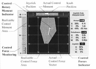
graphical indicators in the Hold Plot Window: |
|||||||
t> The |
same |
actuators |
are |
used for |
control forces (Fore-aft and Athwartships) and |
||
Control Rotary Moment Indicator - presented in the form of a graphical line scaled in % (-100% +100%). The grey rectangle indicates Area of Realizable Control Moment. The white bar represents Actual Control Moment. The yellow symbol indicates knob position (value of control moment set by knob).
l» Control Forces Indicator - is the square scaled in % of fore-aft and athwartships control forces (-100% + 100%). The Grey polygon indicates the Capability Plot of Control Forces (Fore-aft and athwartships) at the present time. Modification of the shape of the Capability Plot during control moment changes is determined by the
- 9 -

Dynamic Positioning System Chapter 3 PRACTICAL OPERATION OF A DP SYSTEM
following:
Control moment generation. Therefore at a fixed control moment, a portion of the actuators' power is already used, and only the remaining actuator power can be used for control force generation.
The Control Forces Indicator also contains:
Actual Control Force vector - white vector from coordinate origin. This vector is always located within the Capability Plot (grey).
Joystick Position - control force vector set by the Joystick (yellow symbol). The set control force vector can't be developed outside of the Capability Plot for a given control moment.
Disturbance Forces vector - green vector from coordinate origin. The following data is represented (in digital form) in the right part of the window:
O Joystick Gain:
^ Normal.
& High.
l> Progressive.
^ Actual control forces and moment in percent and tons: &> Fore-Aft Control force - X.
l> Athwartships Control force - Y. & Yaw Control moment - M.
O Disturbance forces and moment in percent and tons:
fr* |
Fore-Aft disturbance force - X. |
l> |
Athwartships disturbance force - Y. |
^Yaw disturbance moment - M.
^Joystick and knob position in percent.
The following data is represented (in digital form) in the left part of the window:
^ Control Force Monitoring - Graphical indication of Control Forces and Moment, scaled in percent, is located at the left side of the Hold Plot Window. Control Forces and Moment values are represented as vertical bars: "X", "Y" and "M".
^ Color Thruster Allocation Logic (TAL) Indicator (circle) is located to the left of the "XYM" symbols:
8> Green color of TAL Indicator determines presence of distribution.
&• Red color of TAL Indicator indicates absence of even one of Control Forces or Control Moment.
There is an analogous color distribution for Control Force and Moment Indicator symbols:
^Green symbol color:
^"X" - availability of Fore-aft Control force.
|> "Y" - availability of Athwartships Control force.
PARAMETERS WINDOW
These windows are used for input and modification of parameters necessary for the system operation. The windows are divided into the following areas:
Buttons for selection of the parameters group are located in the right part of the window
- 10
Dynamic Positioning System Chapter 3 |
PRACTICAL OPERATION OF A DP SYSTEM |
Parameter values (for the c en group) and editing buttons are located in the left part of the Parameters Window.
Below the set parameter fields, the possible parameter input values are presented (light grey). At the foot of the window, the following buttons are located:
“Apply” – for input of set parameter values. “Cancel” – cancellation of parameters modification. “Default” – input default values.
More detailed description of each parameter group follows.
JOYSTICK PARAMETERS (JST)
The following parameters can be set in this window:
^ Joystick Gain. By selecting the "Change" button it is possible to set the following values: I* Normal — linear relation between Joystick lever and knob movement and force
exerted by the thrusters (and Joystick and knob outputs). Maximum force equals 50% of the available force limit.
9> High - linear relation between Joystick lever and knob movement and force exerted by the thrusters (and Joystick and knob outputs). Maximum force equals 100% of the available force limit.
> Progressive - non-linear (up to 50% as Normal gain and as High gain thereafter), relation between Joystick lever and knob movement and force exerted by the thrusters (and Joystick and knob outputs). Maximum force equals 100% of the available force limit.
<^ Center of Rotation. By selecting the "Change" button it is possible to set the following positions of Center of Rotation:
&» In Bow. l» In Stern.
The set COR value will be used when pressing the "Remote COR" button on the Active Control Panel and also this value will be set in COR Selector by default.
HEADING MODE PARAMETERS (HDG)
This is the J/DP Heading Control group of parameters. The Heading Mode Parameters Window contains the following parameters:
& Rate of turn. This enables an operator to specify the rotation speed to be used by the system when rotating the vessel to a new heading. Using "<" and ">" buttons it is possible to set values from the range: 6, 12, 18, 24, 30, 60, 120 deg/min. <J> Heading Limit. This parameter allows an operator to specify an alarm limit for the heading. The vessel's heading is monitored continuously by the system, and an alarm is given if the limit is exceeded. Using "<" and ">" buttons it is possible to set values from the range: 2, 3, 5, 10, 15, 30 deg.
O Heading Gain is the parameter for Heading Controller sensitivity adjustment. Range of its values is from 1 to 10.
^ Heading Gain value 1 corresponds to low steering accuracy and to small magnitudes
of control moment.
I* Heading Gain value 5 corresponds to standard regulator with good accuracy and
acceptable control activity.
t» Heading Gain value 10 sets maximum steering accuracy but at the expense of
- 11 -
Dynamic Positioning System Chapter 3 |
PRACTICAL OPERATION OF A DP SYSTEM |
frequent steering corrections in heavy seas.
I> In calm weather it is recommended to increase the Heading Gain value for more accurate course holding. In heavy seas it is recommended to decrease the Heading Gain value for reduced actuator operation.
O Set Heading is used to set a new course. By pressing the "Set" button, the Heading Setpoint Window appears, where the new desirable Heading can be entered.
POSITION MODE PARAMETERS (POS)
This is the J/DP Positioning Control group of parameters. The Positioning Mode Parameters Window contains the following parameters:
O Fore-Aft Speed enables an operator to specify the Fore-Aft speed to be used by the IVCS 2000 when moving to a new position. Using "<" and ">" buttons it is possible to set the
required speed value.
^ Athwartships Speed enables an operator to specify the Athwartships speed to be used by the IVCS 2000 when moving to a new position. Using "<" and ">" buttons it is possible
to set the required speed value.
O Position Limit allows an operator to specify an alarm limit for the deviation from the given positioning point. The vessel's position deviation is monitored continuously by the system, and an alarm is given if the limit is exceeded. Using "<" and ">" buttons it is
possible to set one of the values listed below (only in ft).
^ Position Gain is the parameter for Position Controller sensitivity adjustment. Range of its
values is from 1 to 10.
f> Position Gain value 1 corresponds to low positional accuracy and to small magnitude
and frequency of control moment.
|> Position Gain value 5 corresponds to a standard regulator with good accuracy and
acceptable control intensity.
> Position Gain value 10 sets maximum positional accuracy, however the control can
be very intensive, especially in heavy sea conditions.
1> In calm weather it is recommended to increase the Position Gain value for more accurate position keeping. Under heavy sea conditions it is recommended to decrease
the Position Gain value to reduce thruster activity.
« Speed Vector Gain is the parameter for Speed Controller sensitivity adjustment. Range of its values is from 1 to 10.
* Speed Vector Gain value 1 corresponds to slow set speed value monitoring and t
small magnitude and frequency of control moment.
» Speed Vector Gain value 5 corresponds to a standard mode with good accuracy and
acceptable control intensity.
» Speed Vector Gain value 10 sets maximum rate of set speed value monitoring, however the control can be very intensive, especially in heavy sea conditions.
O Set Position is used for setting a new point of positioning. By pressing the "Set" button, the Position Setpoint Window appears, where the new Point of Positioning can be entered.
AP MODE PARAMETERS (AP)
This is the AP Automatic Course Keeping Control group of parameters. This window contains the following parameters:
O Rate of turn. It enables an operator to specify the rate of turn to be used by the system when rotating the vessel to a new heading. Using "<" and ">" buttons, it is possible to set
- 12 -
Dynamic Positioning System Chapter 3 |
PRACTICAL OPERATION OF A DP SYSTEM |
value from the range: 6, 12, 18, 24, 30, 60, 120 deg/min.
O Heading Limit. This parameter allows an operator to specify an alarm limit for the heading. The vessel's heading is monitored continuously by the system, and alarm is given if the limit is exceeded. Using "<" and ">" buttons, it is possible to set value from the range: 2, 3, 5, 10, 15, 30 deg.
O Heading Gain is the parameter for Heading Controller sensitivity adjustment. Range of its values is from 1 to 10.
8> Heading Gain value 1 corresponds to low course accuracy and with small amounts of
steering.
S» Heading Gain value 5 corresponds to standard regulator with good accuracy and
acceptable control activity.
9* Heading Gain value 10 sets maximum course accuracy but with increased steering
activity, especially in heavy seas.
0» At calm weather, it is recommended to increase the Heading Gain for improved course accuracy. In heavy seas it is recommended to reduce the Heading Gain to minimize steering corrections.
<> Rudder Limit. This parameter allows an operator to set rudder angle limits. Using " and ">" buttons. It is possible to set values from the range: 5, 10, 15, 20, 25, 30, 35, 40 deg.
TRACK CONTROL (HIGH SPEED) MODE PARAMETERS:
& Turn Radius. This parameter enables an operator to specify a turn radius for passing a
waypoint in the Track Control (High Speed) Mode.
0- Off track Limit. This parameter is used for setting a distance (from the vessel to a track) within which the vessel can move on either side of the track. When this limit is exceeded,
the system gives an alarm.
0* Track Gain. This parameter is used for Track Controller sensitivity adjustment. Range ot
its values is from 1 to 10.
THRUST LIMITS (THR LIM)
This is a J/DP Mode group of parameters. In this window, an operator can set maximum allowed control signals values for every actuator, which is controlled by TAL. Using "<" and ">" buttons it is possible to set required limit values for each actuator:
^Bow Thrusters.
^Stern Thrusters.
^Propeller Ahead Thrust.
^Propeller Astern Thrust. O' Rudder Limit.
Actuator limits are set in percents from maximum nominal thrust, rudder limit - in degrees.
When changing the Bow Thruster limit, this limit is set for both Bow thrusters at the same time. Stern Thruster limit is set for both bow thrusters at the same time.
The set Actuator Limits are represented on Actuator Indicators in Auto Thr and Man Thr Windows and Capability Diagram Window.
- 13 -
Dynamic Positioning System Chapter 3 |
PRACTICAL OPERATION OF A DP SYSTEM |
ROV FOLLOW MODE PARAMETERS (ROV)
This is the J/DP Positioning Control group of parameters. The ROV Follow Mode Parameters Window contains the following parameters:
O ROV Follow Speed - a constant speed of vessel movement when under ROV follow.
^Reaction Radius (RR), which defines a circle of operation, within which the ROV can move without causing the vessel moving. It only moves when it crosses the boundary of the circle of operation. The center of this circle is the ROV.
^Stop Radius (SR), which is determined as % of RR value.
TRACK CONTROL (LOW SPEED) MODE PARAMETERS (TRACK)
This is J/DP Mode group of parameters. This window contains the following parameters:
0Track Control Strategy: Stop/Non stop. This parameter allows an operator to select one of two possible strategies for waypoints passing in the Track Control (Low Speed) Mode.
^Vessel Speed - setting a constant vessel speed value for movement at Track Control (Low Speed).
01 Off track Limit. This parameter is used for setting a distance (from the vessel to a track) within which the vessel can move on either side of the track. When this limit is exceeded, the system gives an alarm.
^ Track Gain. This parameter is used for Track Controller sensitivity adjustment. Range of its values is from 1 to 10.
VIEW SETTINGS
This parameters group is used for the selection of Position Display configurations and for selecting units of measure. View Settings Window contains the following settings:
O Grid on/off. This is a True View parameter, allowing basic grid according to the selected units of measurement.
^ Sub Grid on/off. This is a True View parameter, with a smaller grid for ease of distance viewing.
<^ Units - units may be selected from the following list: &> m - meters.
If ft-feet.
t* cb - cables (0.1 of nautical mile).
&" Lat. Long, (geo) - setting geographical coordinates on the Position Display. When these units are selected it is impossible to set the Positioning Point offset.
Note, that units' setting also has effect on the "ROV Follow" Window and "Reference Systems" Window.
$ Pallet Day/Night. It is intended for LCD color and brightness changes as appropriate for
day or night viewing.
O Auto View. This is the parameter for setting the Position Display to the re-drawing mode where the vessel silhouette is being re-drawn when approaching the Position Display
boundary ("ON" position).
O View - switching the viewing mode between True/Relative (Earth or Vessel Frame).
O Show DP on/off. Position set point target on/off on the Motion Plot (except for the Auto Positioning Mode).
- 14 -
Dynamic Positioning System Chapter 3 |
PRACTICAL OPERATION OF A DP SYSTEM |
O Show Beacons - switching between showing all beacons and showing only ROV beacon
on the Motion Plot.
0 Scale - imaging scale selection. The range of scaling is 128 - 0.125. The vessel silhouette
on the Position Display is not scaled at small scale.
^ Trace On/Off. This parameter is used to activate display of vessel track on the Position Display, step range ("Step" Softkey): 10, 30, 60, 600, 1800, 3600 sec. Each time
switching to "Trace On", the vessel track is started anew.
NOTE: that only knots are used in the IVCS 2000 as speed units. Parameters #4 - #8 setting is duplicated in the "Position & Heading Display" Window.
SENSORS SETTINGS
This parameters group is used for the selection of HPR type and changing ROV and Reference beacons. These settings can be also changed in the ROV Following Window (see item 0). Also the sensor deviations (constant errors) are shown in this window, but the operator cannot change them. Sensors Window contains the following settings:
O HPR Type - press the respective "Change" button to switch between "Sonardyne", "Simrad", and "ATS II Nautronix" hydro-acoustics.
O Reference Beacon.
0 ROV Beacon - one of the active beacons can be set as ROV or as Reference by pressing the respective "Change" button. Press the "Apply" button to acknowledge.
NOTE: ROV Beacon cannot be changed in the ROV Following Mode. HPR Type and Reference beacon can be changed only when HPR Sensor in the Reference Systems Window is disabled.
POWER LIMITS
In this window, an operator can set maximum allowed power consumption for actuators (thrusters and propellers) and maximum allowed power production for Main Engines and generators. Power limits set in this window are considered by the IVCS 2000 during Thrust Allocation (see item 0). When power consumption/production within these limits is not enough for system operation, an alarm appears. Using "<" and ">" buttons, it is possible to set required limit values for the following actuators:
O Bow #F Thruster.
0 Bow #A Thruster.
^Stern #F Thruster. Q Stern #A Thruster.
^Port Diesel.
^Stbd Diesel.
0 Port Generator.
^Stern Generator. 01 Port Propeller.
^Stbd Propeller.
Power limits are set in percents from maximum consumed/produced power.
Set power limits are indicated in the Power Monitoring Window of the IVCS 2000.
SYSTEM SETTINGS
- 15 -