

A Savelyev DYNAMIC POSITIONING SYSTEM
.pdfDynamic Positioning System Chapter 6 |
POWER GENERATION AND SUPPLY |
||
POWER MONITORING WINDOW |
|
||
The Power Monitoring |
|
||
Window is used for: |
|
||
Thrusters' |
power |
|
|
consumption, |
|
||
parameters |
and |
|
|
state monitoring. |
|
||
Engines' |
and |
|
|
generators' power |
|
||
producing, |
|
|
|
parameters |
and |
|
|
state monitoring. |
|
||
Circuit breakers' |
|
||
state monitoring. |
|
||
Thruster |
|
Motor |
|
Start Preparing,
The following indicators are represented for each thruster, engine, generator, and CPP (Power Monitored Devices):
Power Monitored
Device Image -
Indicates the state otthe Power Monitored Device.
Digital Parameters Indicators - The following group of parameters is monitored for ail Power Monitored Devices, except for the Shaft Generators:
Power.
RPM.
Pitch (except engines).
As for the Shaft Generators, their parameters are the following: Power.
Frequency.
Voltage.
Power Consumption/Generation Graphic Indicator - Shows the consumed/produced power level.
Circuit Breakers Image - Shows the state of the circuit breaker connecting the Power Monitored Device to the bus.
“START” Pushbutton - Is presented only for the thrusters. Enables starting the Thruster Motor Start Preparation Procedure. Changes to the “Ready to start” state after the Preparation Procedure has been executed.
Power Monitored Device Status Indicator - The colored circle Indicator; the color is indicating status: Grey – not ready (option).
White – device under manual control. Green – device under automatic control. Red – device Alarm.
Dynamic Positioning System Chapter 6 |
POWER GENERATION AND SUPPLY |
Power Monitored Group Graphic Bar Indicator - Shows the power consumption and generation for the Power Monitored Device Group.
Red lines on all graphical indicators represent the set power limits.
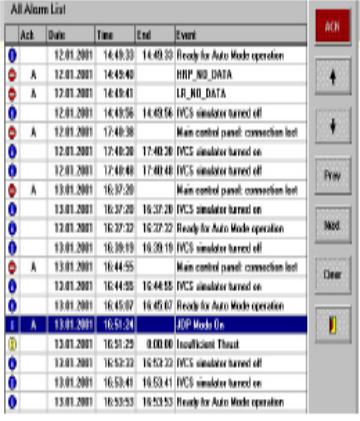
ALARM MONITOR
The Alarm Monitor contains the list of all alarms and control buttons for Alarm List viewing. It can be loaded by one of two ways:
Select “Services Alarm Monitor” option on the Main Screen. Press the “Monitor” Softkey in the Alarm Window of the IVCS2000.
The Alarm Monitor window is similar to the Alarm Window of the IVCS2000. It contains the following: Alarm List, presented as a table, with the following fields in each string:
The symbol, defining message group (Error, Warning, Information). Field of message acknowledgement.
Date.
Time - start Time of alarm. End - stop Time of alarm. Event - text of alarm message.
Control Buttons:
"t" and "i" Softkeys - for alarm selection.
"ACK" Softkey — for acknowledging of selected alarm.
"Prev" and "Next" Softkeys - for moving screen pages (up and down).
"Clear" Softkey - for cleaning of alarms storage. Press this button to keep only 3 months history of alarms.
Dynamic Positioning System Chapter 6 |
POWER GENERATION AND SUPPLY |
Exit Softkey Jj.

Dynamic Positioning System Capter7 OPERATIONS USING DYNAMIC POSITIONING
OPERATIONS USING DYNAMIC POSITIONING
APPROACHING WORKSITE
The Dynamic Positioning Vessel, in many cases, can be considered the command center of the DP operation. Hence, it is imperative that DPOs fully appraise every detail relating to the pending project.
Details to consider prior to arrival at the worksite must include the following: Location and/or parameter of the worksite.
Depth of water at and around the worksite. Traffic in vicinity of worksite. Obstructions above and below the water. Possible hazards relating to DP operation. Weather forecast for the area of operation. Tide and current predictions
Details to consider prior to arrival at the worksite must include the following: Available thrusters.
Equipment redundancy required for the operation.
Available position references and limiting factors (i.e. rigs, platform, and other large structures may interfere with GPS signals). Communication Channel to contact platform or other vessel
involved with DP operation.
Details to consider prior to arriving at the worksite must include the following: Coordinate with engine room (i.e. time, power requirement, communica
tion lights, etc.). Contingency plans for power blackout, abandoning DP operation, exiting worksite, and
more.
TRANSFERRING FROM CONVENTIONAL NAVIGATION TO DP
CONTROL
During the approach to the worksite, the vessel has to switch control from the navigation bridge to the DP console. Several factors must be considered when determining when and where to switch over to the DP console including:
Physical location of the DP console relative to the navigation bridge (i.e. the DP console is in the After Bridge on some vessels. In the case of shutter tankers, the DP console is in the Bow House).
Vessel traffic in the immediate vicinity. Proximity to the 500m zone, if applicable.
The DP system requires some time to build a mathematic model for the prevailing circumstances. Without the model, the vessel will have difficulty maintaining position.
CHECKLIST
Utilizing a checklist for this switching over process will help ensure that essential DP items are examined. A checklist is a guide which lists essential items to be examined. In some cases, the checklist will give the examination sequence and tolerance for the each item.
Generally, the DPO on duty will have to maintain the following checklists: Pre-DP.

Dynamic Positioning System Capter7 OPERATIONS USING DYNAMIC POSITIONING
Pre-operational.
Watch hand-over.
Periodic DP (i.e. every six hours).
NOTE: The Machinery Control Room (MCR), ROV crew, Deck crew, and Surveyors may have their own checklists.
Checklist Recommendations:
If possible, two DPOs should complete the checklist—one reads out and initials each item while the other does the actual check. Avoid racing through the checklist. DP is a gradual process. Use the checklist as a memory aid only so you don’t lose sight of the “big picture.” Update the checklist to reflect modification or upgrade in the DP system. If the checklist is a controlled document, file a non-conformance to get the require change.
SWITCHING FROM MANUAL TO FULL DP MODE
After completing the pre-DP checklist, maneuver the vessel as close to a complete stop as possible, before switching to full DP. Keep in mind that if the vessel still has headway when you switch to full DP, the thrusters may overwork to maintain position. Hence, the vessel could experience a partial or complete blackout, depending on the level of redundancy.
A more practical approach is to engage full DP mode, one axis at a time:
Steady the vessel’s heading prior to pressing the Auto Yaw button. In this mode, the DP system automatically controls the heading. And, the DPO manually controls Sway and Surge with the joystick. This mode is referred to as “JSAH” (Joystick control with Auto Heading).
Manipulate the joystick to reduce motion in the X-axis (fore and aft) as close to zero as possible. Then, engage Auto Surge.
Repeat the above procedure for the Y-axis (sideways) and press Auto Sway.
Caution: Avoid making a heading change, using the Heading Input option, when the vessel has only Auto Yaw and Surge or Auto Yaw and Sway engaged. This could lead to some unsuspected vessel reaction.
LOGBOOK RECORDS
The vessel’s logbook is an official record of pertinent events equivalent to a “black box” in an airplane. As a rule, any information that could be used to reconstruct an operation or incidence for analysis, should be entered into the ship’s logbook.
Some companies have policies relating to what should be recorded in the ship’s log; and, acceptable format to use. In addition, some DP vessels have an automatic voice and event recorder on the bridge.
Events to be recorded in the vessel’s logbook should include, but are not limited to the following:
Essential communication, i.e. permission to proceed into the 500m zone. System failures.
DP incidence and repairs. Details of DP operation.
COMMUNICATION DURING DP OPERATIONS
Any operation that requires successful cooperation between various parties - i.e. charterer, marine department, engineers, surveyors, deck crew, divers, etc.— has the potential for conflict. Communication is crucial to the success of any DP operation.

Dynamic Positioning System Capter7 OPERATIONS USING DYNAMIC POSITIONING
Every single person involved in the DP operation must be briefed about the overall operation in order to see “the big picture.” In addition, it is essential that everyone knows exactly what is expected of him/her.
DP WATCHKEEPING
The nature of the DP operation and class of vessel will dictate manning requirement. For example, a non-redundant DP supply vessel delivering supplies to an oil rig might have only one DPO on watch at a time. However, a construction vessel carrying out dive operation will have at least two DPOs present on the bridge at any time.
Regardless of manning requirements, DPOs on all vessels are involved in hand-over procedures. Some vessels have hand-over checklist. For some vessels, the hand-over is informal.
The following information will greatly enhance the hand-over process: The vessel’s heading and position.
Vessel traffic around the worksite.
Details of the DP operation and expected changes. DP systems performance.
Status of Position Reference Systems and any restriction. Level of redundancy.
Current weather conditions and forecasts. Internal and external communications. Expected helicopter operations.
UTM SYSTEM OF PROJECTION AND COORDINATES
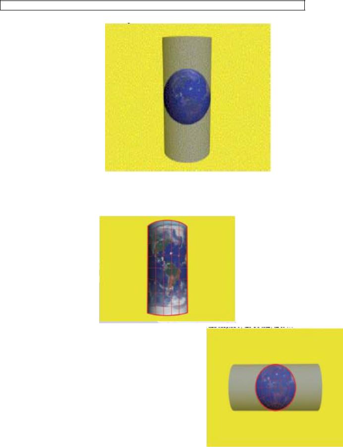
Universal Transverse Mercator (UTM) system of coordinates, produces the high level of accuracy required for most Dynamic Positioning related operations. Hence, UTM is a viable alternative to reduce distortion resulting from the conventional Mercator projection. Mercator Projection is formed by a placing a cylinder tangent to the Earth’s equator.
Lines of longitudes (measured east-west) converging at the poles are stretched in the cylinder so that they are straight and equidistance.
Dynamic Positioning System Capter7 OPERATIONS USING DYNAMIC POSITIONING
Consequently, latitudes (measured north-south) are proportional stretched. Thus, distortion, resulting from the stretching, is minimal at the Equator and increases to a maximum value at the poles.
Since, most DP operations are carried out well away from the equator, a more accurate system of coordinates was needed— UTM. In the UTM system of coordinates, Northings and Eastings, measured in meters, are used to express a position. Universal Transverse Mercator (UTM) was developed in 1936 and adopted by the US army in 1947.
Dynamic Positioning System Capter7 OPERATIONS USING DYNAMIC POSITIONING
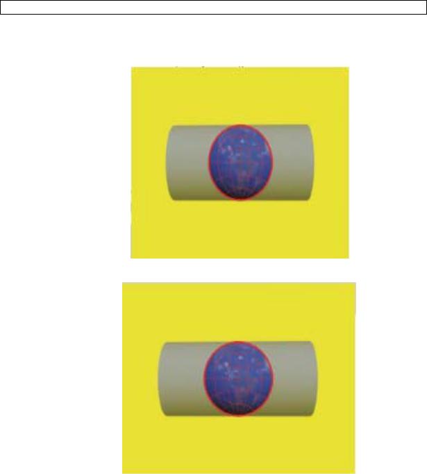
This projection is based on a cylinder placed tangent to a selected meridian.
Thus, the area within 3º on each side of the selected meridian has minimal distortion.
A single Transverse Mercator projection only yields a useful zone of 6º width of longitude (3º on each side of the selected meridian). Hence, that is obviously not enough to cover the whole terrestrial sphere without distortion. Consequently, the cylinder is rotated in 60 steps (six degrees per step) UTM to ensure every point on Earth is within 3 degrees of a central meridian. In addition, each zone is then divided into 100,000 meter squares (100 000 x 100 000).

Dynamic Positioning System Capter7 OPERATIONS USING DYNAMIC POSITIONING
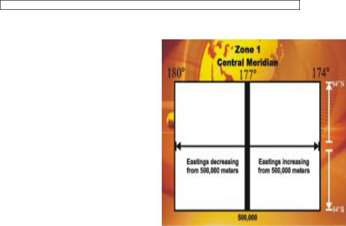
In order to cover the entire Earth, the terrestrial sphere is divided into 60 zones of 6º longitude. The zones start at 180º meridian and are numbered consecutively eastward.
THE ZONES ALSO EXTEND FROM 84º N TO 80º S.
Dynamic Positioning System Capter7 OPERATIONS USING DYNAMIC POSITIONING
Zone 1, for example extends from 180º meridian to 174º W longitude, with the central meridian at 177ºW). Eastings are measured increasing to the east. In
addition, the central meridian is given a false datum value of 500,000. Hence, Eastings for a position east of the central meridian will increase from 500,000 to the position.
Eastings for a position west of the central meridian will decrease from 500,000 to the position. This resolution results in positive Eastings values throughout the zone.
Northings are measured increasing to the north. For example, the Northings for a position in the Northern hemisphere is measured from the Equator (zero reference) northward to the position.
Northings for a position in the Southern hemisphere is measured from the Equator. However, in this case, the Equator is given a false datum of 10,000,000. Hence, Northings value decrease from the Equator southward. This resolution results in positive Northings values increasing northward throughout the globe.
Advantages of UTM Systems of Coordinates: Minimal distortion within a zone.
High accuracy.
Accuracy is consistent throughout the glove. UTM is popular in DP operations.
Disadvantages of UTM System of Coordinates:
High distortion at the poles.
Northings and Easting are measured from false origins.
A complete reference requires Northings, zone number, and Eastings.
Combining different UTM zones lead to major distortion.
DATUMS USED IN DP OPERATIONS
Three popular datums used in DP operations:
Universal Transverse Mercator (UTM ) system gives position in terms of zone number, Northings and Eastings in meters.
Latitude and Longitude coordinates system, give position in terms of North or South and East or West relative to the Equator and Greenwich meridian respectively. Coordinates are given in degrees and minutes.
Local coordinates system gives position in terms of distances North/South (X) and East/West (Y) from a local reference point—fanbeam reflector, HPR transponder, taut wire depressor weight location, etc.
DIAGRAM BASED ON UTM COORDINATES