

- •Verilog-AMS
- •Language Reference Manual
- •Table of Contents
- •1. Verilog-AMS introduction
- •1.1 Overview
- •1.2 Mixed-signal language features
- •1.3 Systems
- •1.3.1 Conservative systems
- •1.3.1.1 Reference nodes
- •1.3.1.2 Reference directions
- •1.3.2 Kirchhoff’s Laws
- •1.3.3 Natures, disciplines, and nets
- •1.3.4 Signal-flow systems
- •1.3.5 Mixed conservative/signal flow systems
- •1.4 Conventions used in this document
- •1.5 Contents
- •2. Lexical conventions
- •2.1 Overview
- •2.2 Lexical tokens
- •2.3 White space
- •2.4 Comments
- •2.5 Operators
- •2.6 Numbers
- •2.6.1 Integer constants
- •2.6.2 Real constants
- •2.7 String literals
- •2.8 Identifiers, keywords, and system names
- •2.8.1 Escaped identifiers
- •2.8.2 Keywords
- •2.8.3 System tasks and functions
- •2.8.4 Compiler directives
- •2.9 Attributes
- •2.9.1 Standard attributes
- •2.9.2 Syntax
- •3. Data types
- •3.1 Overview
- •3.2 Integer and real data types
- •3.2.1 Output variables
- •3.3 String data type
- •3.4 Parameters
- •3.4.1 Type specification
- •3.4.2 Value range specification
- •3.4.3 Parameter units and descriptions
- •3.4.4 Parameter arrays
- •3.4.5 Local parameters
- •3.4.6 String parameters
- •3.4.7 Parameter aliases
- •3.5 Genvars
- •3.6 Net_discipline
- •3.6.1 Natures
- •3.6.1.1 Derived natures
- •3.6.1.2 Attributes
- •3.6.1.3 User-defined attributes
- •3.6.2 Disciplines
- •3.6.2.1 Nature binding
- •3.6.2.2 Domain binding
- •3.6.2.3 Empty disciplines
- •3.6.2.4 Discipline of nets and undeclared nets
- •3.6.2.5 Overriding nature attributes from discipline
- •3.6.2.6 Deriving natures from disciplines
- •3.6.2.7 User-defined attributes
- •3.6.3 Net discipline declaration
- •3.6.3.1 Net descriptions
- •3.6.3.2 Net Discipline Initial (Nodeset) Values
- •3.6.4 Ground declaration
- •3.6.5 Implicit nets
- •3.7 Real net declarations
- •3.8 Default discipline
- •3.9 Disciplines of primitives
- •3.10 Discipline precedence
- •3.11 Net compatibility
- •3.11.1 Discipline and Nature Compatibility
- •3.12 Branches
- •3.13 Namespace
- •3.13.1 Nature and discipline
- •3.13.2 Access functions
- •3.13.4 Branch
- •4. Expressions
- •4.1 Overview
- •4.2 Operators
- •4.2.1 Operators with real operands
- •4.2.1.1 Real to integer conversion
- •4.2.1.2 Integer to real conversion
- •4.2.1.3 Arithmetic conversion
- •4.2.2 Operator precedence
- •4.2.3 Expression evaluation order
- •4.2.4 Arithmetic operators
- •4.2.5 Relational operators
- •4.2.6 Case equality operators
- •4.2.7 Logical equality operators
- •4.2.8 Logical operators
- •4.2.9 Bitwise operators
- •4.2.10 Reduction operators
- •4.2.11 Shift operators
- •4.2.12 Conditional operator
- •4.2.13 Concatenations
- •4.3 Built-in mathematical functions
- •4.3.1 Standard mathematical functions
- •4.3.2 Transcendental functions
- •4.4 Signal access functions
- •4.5 Analog operators
- •4.5.1 Vector or array arguments to analog operators
- •4.5.2 Analog operators and equations
- •4.5.3 Time derivative operator
- •4.5.4 Time integral operator
- •4.5.5 Circular integrator operator
- •4.5.6 Derivative operator
- •4.5.7 Absolute delay operator
- •4.5.8 Transition filter
- •4.5.9 Slew filter
- •4.5.10 last_crossing function
- •4.5.11 Laplace transform filters
- •4.5.11.1 laplace_zp
- •4.5.11.2 laplace_zd
- •4.5.11.3 laplace_np
- •4.5.11.4 laplace_nd
- •4.5.11.5 Examples
- •4.5.12 Z-transform filters
- •4.5.13 Limited exponential
- •4.5.14 Constant versus dynamic arguments
- •4.5.15 Restrictions on analog operators
- •4.6 Analysis dependent functions
- •4.6.1 Analysis
- •4.6.2 DC analysis
- •4.6.3 AC stimulus
- •4.6.4 Noise
- •4.6.4.1 white_noise
- •4.6.4.2 flicker_noise
- •4.6.4.3 noise_table
- •4.6.4.4 Noise model for diode
- •4.6.4.5 Correlated noise
- •4.7 User defined functions
- •4.7.1 Defining an analog user defined function
- •4.7.2 Returning a value from an analog user defined function
- •4.7.2.1 Analog user defined function identifier variable
- •4.7.2.2 Output arguments
- •4.7.2.3 Inout arguments
- •4.7.3 Calling an analog user defined function
- •5. Analog behavior
- •5.1 Overview
- •5.2 Analog procedural block
- •5.2.1 Analog initial block
- •5.3 Block statements
- •5.3.1 Sequential blocks
- •5.3.2 Block names
- •5.4 Analog signals
- •5.4.1 Access functions
- •5.4.2 Probes and sources
- •5.4.2.1 Probes
- •5.4.2.2 Sources
- •5.4.3 Port branches
- •5.4.4 Unassigned sources
- •5.5 Accessing net and branch signals and attributes
- •5.5.1 Accessing net and branch signals
- •5.5.2 Signal access for vector branches
- •5.5.3 Accessing attributes
- •5.6 Contribution statements
- •5.6.1 Direct branch contribution statements
- •5.6.1.1 Relations
- •5.6.1.2 Evaluation
- •5.6.1.3 Value retention
- •5.6.2 Examples
- •5.6.2.1 The four controlled sources
- •5.6.3 Resistor and conductor
- •5.6.4 RLC circuits
- •5.6.5 Switch branches
- •5.6.6 Implicit Contributions
- •5.6.7 Indirect branch contribution statements
- •5.6.7.1 Multiple indirect contributions
- •5.6.7.2 Indirect and direct contribution
- •5.7 Analog procedural assignments
- •5.8 Analog conditional statements
- •5.8.1 if-else-if statement
- •5.8.2 Examples
- •5.8.3 Case statement
- •5.8.4 Restrictions on conditional statements
- •5.9 Looping statements
- •5.9.1 Repeat and while statements
- •5.9.2 For statements
- •5.9.3 Analog For Statements
- •5.10 Analog event control statements
- •5.10.1 Event OR operator
- •5.10.2 Global events
- •5.10.3 Monitored events
- •5.10.3.1 cross function
- •5.10.3.2 above function
- •5.10.3.3 timer function
- •5.10.4 Named events
- •5.10.5 Digital events in analog behavior
- •6. Hierarchical structures
- •6.1 Overview
- •6.2 Modules
- •6.2.1 Top-level modules
- •6.2.2 Module instantiation
- •6.3 Overriding module parameter values
- •6.3.1 Defparam statement
- •6.3.2 Module instance parameter value assignment by order
- •6.3.3 Module instance parameter value assignment by name
- •6.3.4 Parameter dependence
- •6.3.5 Detecting parameter overrides
- •6.3.6 Hierarchical system parameters
- •6.4 Paramsets
- •6.4.1 Paramset statements
- •6.4.2 Paramset overloading
- •6.4.3 Paramset output variables
- •6.5 Ports
- •6.5.1 Port definition
- •6.5.2 Port declarations
- •6.5.2.1 Port type
- •6.5.2.2 Port direction
- •6.5.3 Real valued ports
- •6.5.4 Connecting module ports by ordered list
- •6.5.5 Connecting module ports by name
- •6.5.6 Detecting port connections
- •6.5.7 Port connection rules
- •6.5.7.1 Matching size rule
- •6.5.7.2 Resolving discipline of undeclared interconnect signal
- •6.5.8 Inheriting port natures
- •6.6 Generate constructs
- •6.6.1 Loop generate constructs
- •6.6.2 Conditional generate constructs
- •6.6.2.1 Dynamic parameters
- •6.6.3 External names for unnamed generate blocks
- •6.7 Hierarchical names
- •6.7.1 Usage of hierarchical references
- •6.8 Scope rules
- •6.9 Elaboration
- •6.9.1 Concatenation of analog blocks
- •6.9.2 Elaboration and paramsets
- •6.9.3 Elaboration and connectmodules
- •6.9.4 Order of elaboration
- •7. Mixed signal
- •7.1 Overview
- •7.2 Fundamentals
- •7.2.1 Domains
- •7.2.2 Contexts
- •7.2.3 Nets, nodes, ports, and signals
- •7.2.4 Mixed-signal and net disciplines
- •7.3 Behavioral interaction
- •7.3.1 Accessing discrete nets and variables from a continuous context
- •7.3.2 Accessing X and Z bits of a discrete net in a continuous context
- •7.3.2.1 Special floating point values
- •7.3.3 Accessing continuous nets and variables from a discrete context
- •7.3.4 Detecting discrete events in a continuous context
- •7.3.5 Detecting continuous events in a discrete context
- •7.3.6 Concurrency
- •7.3.6.1 Analog event appearing in a digital event control
- •7.3.6.2 Digital event appearing in an analog event control
- •7.3.6.3 Analog primary appearing in a digital expression
- •7.3.6.4 Analog variables appearing in continuous assigns
- •7.3.6.5 Digital primary appearing in an analog expression
- •7.3.7 Function calls
- •7.4 Discipline resolution
- •7.4.1 Compatible discipline resolution
- •7.4.2 Connection of discrete-time disciplines
- •7.4.3 Connection of continuous-time disciplines
- •7.4.4 Resolution of mixed signals
- •7.4.4.1 Basic discipline resolution algorithm
- •7.4.4.2 Detail discipline resolution algorithm
- •7.4.4.3 Coercing discipline resolution
- •7.5 Connect modules
- •7.6 Connect module descriptions
- •7.7 Connect specification statements
- •7.7.1 Connect module auto-insertion statement
- •7.7.2 Discipline resolution connect statement
- •7.7.2.1 Connect Rule Resolution Mechanism
- •7.7.3 Parameter passing attribute
- •7.7.4 connect_mode
- •7.8 Automatic insertion of connect modules
- •7.8.1 Connect module selection
- •7.8.2 Signal segmentation
- •7.8.3 connect_mode parameter
- •7.8.3.1 merged
- •7.8.3.2 split
- •7.8.4 Rules for driver-receiver segregation and connect module selection and insertion
- •7.8.5 Instance names for auto-inserted instances
- •7.8.5.1 Port names for Verilog built-in primitives
- •8. Scheduling semantics
- •8.1 Overview
- •8.2 Analog simulation cycle
- •8.2.1 Nodal analysis
- •8.2.2 Transient analysis
- •8.2.3 Convergence
- •8.3 Mixed-signal simulation cycle
- •8.3.1 Circuit initialization
- •8.3.2 Mixed-signal DC analysis
- •8.3.3 Mixed-signal transient analysis
- •8.3.3.1 Concurrency
- •8.3.3.2 Analog macro process scheduling semantics
- •8.3.3.3 A/D boundary timing
- •8.3.4 The synchronization loop
- •8.3.5 Synchronization and communication algorithm
- •8.3.6 Assumptions about the analog and digital algorithms
- •8.4 Scheduling semantics for the digital engine
- •8.4.1 The stratified event queue
- •8.4.2 The Verilog-AMS digital engine reference model
- •8.4.3 Scheduling implication of assignments
- •8.4.3.1 Continuous assignment
- •8.4.3.2 Procedural continuous assignment
- •8.4.3.3 Blocking assignment
- •8.4.3.4 Non blocking assignment
- •8.4.3.5 Switch (transistor) processing
- •8.4.3.6 Processing explicit D2A events (region 1b)
- •8.4.3.7 Processing analog macro-process events (region 3b)
- •9. System tasks and functions
- •9.1 Overview
- •9.2 Categories of system tasks and functions
- •9.3 System tasks/functions executing in the context of the Analog Simulation Cycle
- •9.4 Display system tasks
- •9.4.1 Behavior of the display tasks in the analog context
- •9.4.2 Escape sequences for special characters
- •9.4.3 Format specifications
- •9.4.4 Hierarchical name format
- •9.4.5 String format
- •9.4.6 Behavior of the display tasks in the analog block during iterative solving
- •9.4.7 Extensions to the display tasks in the digital context
- •9.5.1 Opening and closing files
- •9.5.1.1 opening and closing files during multiple analyses
- •9.5.1.2 Sharing of file descriptors between the analog and digital contexts
- •9.5.2 File output system tasks
- •9.5.3 Formatting data to a string
- •9.5.4 Reading data from a file
- •9.5.4.1 Reading a line at a time
- •9.5.4.2 Reading formatted data
- •9.5.5 File positioning
- •9.5.6 Flushing output
- •9.5.7 I/O error status
- •9.5.8 Detecting EOF
- •9.5.9 Behavior of the file I/O tasks in the analog block during iterative solving
- •9.6 Timescale system tasks
- •9.7 Simulation control system tasks
- •9.7.1 $finish
- •9.7.2 $stop
- •9.7.3 $fatal, $error, $warning, and $info
- •9.8 PLA modeling system tasks
- •9.9 Stochastic analysis system tasks
- •9.10 Simulator time system functions
- •9.11 Conversion system functions
- •9.12 Command line input
- •9.13 Probabilistic distribution system functions
- •9.13.1 $random and $arandom
- •9.13.2 distribution functions
- •9.13.3 Algorithm for probablistic distribution
- •9.14 Math system functions
- •9.15 Analog kernel parameter system functions
- •9.16 Dynamic simulation probe function
- •9.17 Analog kernel control system tasks and functions
- •9.17.1 $discontinuity
- •9.17.2 $bound_step task
- •9.17.3 $limit
- •9.18 Hierarchical parameter system functions
- •9.19 Explicit binding detection system functions
- •9.20 Table based interpolation and lookup system function
- •9.20.1 Table data source
- •9.20.2 Control string
- •9.20.3 Example control strings
- •9.20.4 Lookup algorithm
- •9.20.5 Interpolation algorithms
- •9.20.6 Example
- •9.21 Connectmodule driver access system functions and operator
- •9.21.1 $driver_count
- •9.21.2 $driver_state
- •9.21.3 $driver_strength
- •9.21.4 driver_update
- •9.21.5 Receiver net resolution
- •9.21.6 Connect module example using driver access functions
- •9.22 Supplementary connectmodule driver access system functions
- •9.22.1 $driver_delay
- •9.22.2 $driver_next_state
- •9.22.3 $driver_next_strength
- •9.22.4 $driver_type
- •10. Compiler directives
- •10.1 Overview
- •10.2 `default_discipline
- •10.3 `default_transition
- •10.4 `define and `undef
- •10.5 Predefined macros
- •10.6 `begin_keywords and `end_keywords
- •11. Using VPI routines
- •11.1 Overview
- •11.2 The VPI interface
- •11.2.1 VPI callbacks
- •11.2.2 VPI access to Verilog-AMS HDL objects and simulation objects
- •11.2.3 Error handling
- •11.3 VPI object classifications
- •11.3.1 Accessing object relationships and properties
- •11.3.2 Delays and values
- •11.4 List of VPI routines by functional category
- •11.5 Key to object model diagrams
- •11.5.1 Diagram key for objects and classes
- •11.5.2 Diagram key for accessing properties
- •11.5.3 Diagram key for traversing relationships
- •11.6 Object data model diagrams
- •11.6.1 Module
- •11.6.2 Nature, discipline
- •11.6.3 Scope, task, function, IO declaration
- •11.6.4 Ports
- •11.6.5 Nodes
- •11.6.6 Branches
- •11.6.7 Quantities
- •11.6.8 Nets
- •11.6.9 Regs
- •11.6.10 Variables, named event
- •11.6.11 Memory
- •11.6.12 Parameter, specparam
- •11.6.13 Primitive, prim term
- •11.6.15 Module path, timing check, intermodule path
- •11.6.16 Task and function call
- •11.6.17 Continuous assignment
- •11.6.18 Simple expressions
- •11.6.19 Expressions
- •11.6.20 Contribs
- •11.6.21 Process, block, statement, event statement
- •11.6.22 Assignment, delay control, event control, repeat control
- •11.6.23 If, if-else, case
- •11.6.24 Assign statement, deassign, force, release, disable
- •11.6.25 Callback, time queue
- •12. VPI routine definitions
- •12.1 Overview
- •12.2 vpi_chk_error()
- •12.3 vpi_compare_objects()
- •12.4 vpi_free_object()
- •12.6 vpi_get_cb_info()
- •12.7 vpi_get_analog_delta()
- •12.8 vpi_get_analog_freq()
- •12.9 vpi_get_analog_time()
- •12.10 vpi_get_analog_value()
- •12.11 vpi_get_delays()
- •12.13 vpi_get_analog_systf_info()
- •12.14 vpi_get_systf_info()
- •12.15 vpi_get_time()
- •12.16 vpi_get_value()
- •12.17 vpi_get_vlog_info()
- •12.18 vpi_get_real()
- •12.19 vpi_handle()
- •12.20 vpi_handle_by_index()
- •12.21 vpi_handle_by_name()
- •12.22 vpi_handle_multi()
- •12.22.1 Derivatives for analog system task/functions
- •12.22.2 Examples
- •12.23 vpi_iterate()
- •12.24 vpi_mcd_close()
- •12.25 vpi_mcd_name()
- •12.26 vpi_mcd_open()
- •12.27 vpi_mcd_printf()
- •12.28 vpi_printf()
- •12.29 vpi_put_delays()
- •12.30 vpi_put_value()
- •12.31 vpi_register_cb()
- •12.31.1 Simulation-event-related callbacks
- •12.31.2 Simulation-time-related callbacks
- •12.31.3 Simulator analog and related callbacks
- •12.31.4 Simulator action and feature related callbacks
- •12.32 vpi_register_analog_systf()
- •12.32.1 System task and function callbacks
- •12.32.2 Declaring derivatives for analog system task/functions
- •12.32.3 Examples
- •12.33 vpi_register_systf()
- •12.33.1 System task and function callbacks
- •12.33.2 Initializing VPI system task/function callbacks
- •12.34 vpi_remove_cb()
- •12.35 vpi_scan()
- •12.36 vpi_sim_control()
- •A.1 Source text
- •A.1.1 Library source text
- •A.1.2 Verilog source text
- •A.1.3 Module parameters and ports
- •A.1.4 Module items
- •A.1.5 Configuration source text
- •A.1.6 Nature Declaration
- •A.1.7 Discipline Declaration
- •A.1.8 Connectrules Declaration
- •A.1.9 Paramset Declaration
- •A.2 Declarations
- •A.2.1 Declaration types
- •A.2.1.1 Module parameter declarations
- •A.2.1.2 Port declarations
- •A.2.1.3 Type declarations
- •A.2.2 Declaration data types
- •A.2.2.1 Net and variable types
- •A.2.2.2 Strengths
- •A.2.2.3 Delays
- •A.2.3 Declaration lists
- •A.2.4 Declaration assignments
- •A.2.5 Declaration ranges
- •A.2.6 Function declarations
- •A.2.7 Task declarations
- •A.2.8 Block item declarations
- •A.3 Primitive instances
- •A.3.1 Primitive instantiation and instances
- •A.3.2 Primitive strengths
- •A.3.3 Primitive terminals
- •A.3.4 Primitive gate and switch types
- •A.4 Module instantiation and generate construct
- •A.4.1 Module instantiation
- •A.4.2 Generate construct
- •A.5 UDP declaration and instantiation
- •A.5.1 UDP declaration
- •A.5.2 UDP ports
- •A.5.3 UDP body
- •A.5.4 UDP instantiation
- •A.6 Behavioral statements
- •A.6.1 Continuous assignment statements
- •A.6.2 Procedural blocks and assignments
- •A.6.3 Parallel and sequential blocks
- •A.6.4 Statements
- •A.6.5 Timing control statements
- •A.6.6 Conditional statements
- •A.6.7 Case statements
- •A.6.8 Looping statements
- •A.6.9 Task enable statements
- •A.6.10 Contribution statements
- •A.7 Specify section
- •A.7.1 Specify block declaration
- •A.7.2 Specify path declarations
- •A.7.3 Specify block terminals
- •A.7.4 Specify path delays
- •A.7.5 System timing checks
- •A.7.5.1 System timing check commands
- •A.7.5.2 System timing check command arguments
- •A.7.5.3 System timing check event definitions
- •A.8 Expressions
- •A.8.1 Concatenations
- •A.8.2 Function calls
- •A.8.3 Expressions
- •A.8.4 Primaries
- •A.8.5 Expression left-side values
- •A.8.6 Operators
- •A.8.7 Numbers
- •A.8.8 Strings
- •A.8.9 Analog references
- •A.9 General
- •A.9.1 Attributes
- •A.9.2 Comments
- •A.9.3 Identifiers
- •A.9.4 White space
- •A.10 Details
- •C.1 Verilog-AMS introduction
- •C.1.1 Verilog-A overview
- •C.1.2 Verilog-A language features
- •C.2 Lexical conventions
- •C.3 Data types
- •C.4 Expressions
- •C.5 Analog signals
- •C.6 Analog behavior
- •C.7 Hierarchical structures
- •C.8 Mixed signal
- •C.9 Scheduling semantics
- •C.10 System tasks and functions
- •C.11 Compiler directives
- •C.12 Using VPI routines
- •C.13 VPI routine definitions
- •C.14 Analog language subset
- •C.15 List of keywords
- •C.16 Standard definitions
- •C.17 SPICE compatibility
- •C.18 Changes from previous Verilog-A LRM versions
- •C.19 Obsolete functionality
- •D.1 The disciplines.vams file
- •D.2 The constants.vams file
- •D.3 The driver_access.vams file
- •E.1 Introduction
- •E.1.1 Scope of compatibility
- •E.1.2 Degree of incompatibility
- •E.2 Accessing Spice objects from Verilog-AMS HDL
- •E.2.1 Case sensitivity
- •E.2.2 Examples
- •E.3 Accessing Spice models
- •E.3.1 Accessing Spice subcircuits
- •E.3.1.1 Accessing Spice primitives
- •E.4 Preferred primitive, parameter, and port names
- •E.4.1 Unsupported primitives
- •E.4.2 Discipline of primitives
- •E.4.2.1 Setting the discipline of analog primitives
- •E.4.2.2 Resolving the disciplines of analog primitives
- •E.4.3 Name scoping of SPICE primitives
- •E.4.4 Limiting algorithms
- •E.5 Other issues
- •E.5.1 Multiplicity factor on subcircuits
- •E.5.2 Binning and libraries
- •F.1 Discipline resolution
- •F.2 Resolution of mixed signals
- •F.2.1 Default discipline resolution algorithm
- •F.2.2 Alternate expanded analog discipline resolution algorithm
- •G.1 Changes from previous LRM versions
- •G.2 Obsolete functionality
- •G.2.1 Forever
- •G.2.2 NULL
- •G.2.3 Generate
- •G.2.4 `default_function_type_analog
Accellera |
|
|
|
|
Version 2.3.1, June 1, 2009 |
|
|
VERILOG-AMS |
|
12.12 vpi_get_str() |
|
|
|
|
|
|
|
|
|
|
|
|
vpi_get_str() |
|
|
|
|
|
|
Synopsis: |
Get the value of a string property of an object. |
|||
|
|
|
|
|
Syntax: |
vpi_get_str(prop, obj) |
|
|
|
|
|
|
|
|
|
Type |
Description |
|
|
Returns: |
|
|
|
|
char * |
Pointer to a character string containing the property value |
|||
|
|
|
|
|
|
Type |
Name |
|
Description |
Arguments: |
|
|
|
|
int |
prop |
|
An integer constant representing the property of an object |
|
|
|
|
|
for which to obtain a value |
|
|
|
|
|
|
vpiHandle |
obj |
|
Handle to an object |
|
|
|
|
|
Related |
Use vpi_get() to get integer and Boolean properties |
|||
routines: |
|
|
|
|
|
|
|
|
|
|
|
|
|
|
The VPI routine vpi_get_str() shall return string property values. The string shall be placed in a temporary buffer which shall be used by every call to this routine. If the string is to be used after a subsequent call, the string needs to be copied to another location. A different string buffer shall be used for string values returned through the s_vpi_value structure.
The following example illustrates the usage of vpi_get_str().
char *str;
vpiHandle mod = vpi_handle_by_name("top.mod1",NULL); vpi_printf ("Module top.mod1 is an instance of %s\n",
vpi_get_str(vpiDefName, mod));
12.13 vpi_get_analog_systf_info()
vpi_get_analog_systf_info()
Synopsis: Retrieve information about a user-defined analog system task/function-related callback.
Syntax: vpi_get_analog_systf_info(obj, systf_data_p)
|
Type |
Description |
|
Returns: |
|
|
|
void |
|
|
|
|
|
|
|
|
Type |
Name |
Description |
Arguments: |
|
|
|
vpiHandle |
obj |
Handle to a system task/function-related callback |
|
|
|
|
|
|
p_vpi_analog_sy |
systf_data_p |
Pointer to a structure containing callback information |
|
stf_data |
|
|
|
|
|
|
Related |
Use vpi_get_cb_info() to retrieve information about a simulation-related callback |
||
routines: |
|
|
|
|
|
|
|
Copyright © 2009 Accellera Organization, Inc. |
288 |
|
Accellera |
Analog and Mixed-signal Extensions to Verilog HDL |
Version 2.3.1, June 1, 2009 |
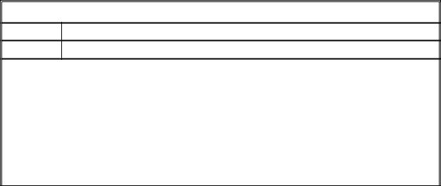
The VPI routine vpi_get_analog_systf_info() shall return information about a user-defined analog system task or function callback in an s_vpi_analog_systf_data structure. The memory for this structure shall be allocated by the user.
The s_vpi_systf_data structure used by vpi_get_analog_systf_info() is defined in vpi_user.h and is listed in Figure 12-6.
typedef struct t_vpi_analog_systf_data {
int type; |
/* vpiSys[Task,Function] */ |
int sysfunctype; |
/* vpi[IntFunc,RealFunc,TimeFunc,SizedFunc] */ |
char *tfname; |
/* first character shall be “$” */ |
int (*calltf)(); |
|
int (*compiletf)(); |
|
int (*sizetf)(); |
/* for vpiSizedFunc system functions only */ |
p_vpi_stf_partials (*derivtf)(); /* for partial derivatives */ char *user_data;
} s_vpi_analog_systf_data, *p_vpi_analog_systf_data;
Figure 12-6: The s_vpi_systf_data structure definition
12.14 vpi_get_systf_info()
vpi_get_systf_info()
Synopsis: Retrieve information about a user-defined system task/function-related callback.
Syntax: vpi_get_systf_info(obj, systf_data_p)
|
Type |
Description |
|
Returns: |
|
|
|
void |
|
|
|
|
|
|
|
|
Type |
Name |
Description |
Arguments: |
|
|
|
vpiHandle |
obj |
Handle to a system task/function-related callback |
|
|
|
|
|
|
p_vpi_systf_data |
systf_data_p |
Pointer to a structure containing callback information |
|
|
|
|
Related |
Use vpi_get_cb_info() to retrieve information about a simulation-related callback |
||
routines: |
|
|
|
|
|
|
|
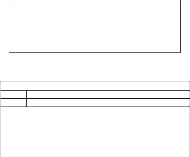
The VPI routine vpi_get_systf_info() shall return information about a user-defined system task or function callback in an s_vpi_systf_data structure. The memory for this structure shall be allocated by the user.
The s_vpi_systf_data structure used by vpi_get_systf_info() is defined in vpi_user.h and is listed in Figure 12-7.
289 |
Copyright © 2009 Accellera Organization, Inc. All rights reserved. |

Accellera |
|
Version 2.3.1, June 1, 2009 |
VERILOG-AMS |
typedef struct t_vpi_systf_data {
int type; |
/* vpiSys[Task,Function] */ |
int sysfunctype; |
/* vpi[IntFunc,RealFunc,TimeFunc,SizedFunc] */ |
char *tfname; |
/* first character shall be “$” */ |
int (*calltf)(); |
|
int (*compiletf)(); |
|
int (*sizetf)(); |
/* for vpiSizedFunc system functions only */ |
char *user_data;
} s_vpi_systf_data, *p_vpi_systf_data;
Figure 12-7: The s_vpi_systf_data structure definition
12.15 vpi_get_time()
|
|
|
|
|
|
|
|
vpi_get_time() |
|
|
|
|
|
|
Synopsis: |
Retrieve the current simulation. |
|
|
|
|
|
|
|
|
Syntax: |
vpi_get_time(obj, time_p) |
|
|
|
|
|
|
|
|
|
Type |
Description |
|
|
Returns: |
|
|
|
|
void |
|
|
|
|
|
|
|
|
|
|
Type |
Name |
|
Description |
Arguments: |
|
|
|
|
vpiHandle |
obj |
|
Handle to an object |
|
|
|
|
|
|
|
p_vpi_time |
time_p |
|
Pointer to a structure containing time information |
|
|
|
|
|
Related |
|
|
|
|
routines: |
|
|
|
|
|
|
|
|
|
|
|
|
|
|
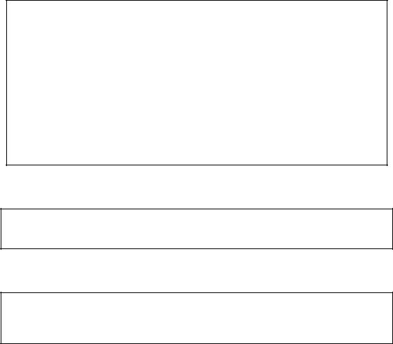
The VPI routine vpi_get_time() shall retrieve the current simulation time, using the time scale of the object. If obj is NULL, the simulation time is retrieved using the simulation time unit. The time_p->type field shall be set to indicate if scaled real, analog, or simulation time is desired. The memory for the time_p structure shall be allocated by the user.
The s_vpi_time structure used by vpi_get_time() is defined in vpi_user.h and is listed in Figure 12-8 (this is the same time structure as used by vpi_put_value()).
typedef struct t_vpi_time { |
|
|
int type; |
/* for vpiScaledRealTime, vpiSimTime, |
|
vpiAnalogTime */ |
|
|
unsigned int high, low; |
/* for vpiSimTime */ |
|
double real; |
/* for vpiScaledRealTime */ |
|
} s_vpi_time, *p_vpi_time; |
|
|
Figure 12-8: The s_vpi_time structure definition
Copyright © 2009 Accellera Organization, Inc. |
290 |
|
|
|
|
Accellera |
Analog and Mixed-signal Extensions to Verilog HDL |
Version 2.3.1, June 1, 2009 |
|||
12.16 vpi_get_value() |
|
|
|
|
|
|
|
||
|
|
vpi_get_value() |
||
|
|
|
|
|
Synopsis: |
Retrieve the simulation value of an object. |
|
||
|
|
|
||
Syntax: |
vpi_get_value(obj, value_p) |
|
||
|
|
|
|
|
|
Type |
Description |
|
|
Returns: |
|
|
|
|
void |
|
|
|
|
|
|
|
|
|
|
Type |
Name |
Description |
|
Arguments: |
|
|
|
|
vpiHandle |
obj |
|
Handle to an expression |
|
|
|
|
|
|
|
p_vpi_value |
value_p |
|
Pointer to a structure containing value information |
|
|
|
|
|
Related |
Use vpi_get_analog_value() for simulation value of quantity objects. |
|||
routines: |
Use vpi_put_value() to set the value of an object |
|
||
|
|
|
|
|
|
|
|
|
|
The VPI routine vpi_get_value() shall retrieve the simulation value of VPI objects (use vpi_get_analog_value() for the simulation value of VPI analog quantity objects). The value shall be placed in an s_vpi_value structure, which has been allocated by the user. The format of the value shall be set by the format field of the structure.
When the format field is vpiObjTypeVal, the routine shall fill in the value and change the format field based on the object type, as follows:
—For an integer, vpiIntVal
—For a real, vpiRealVal
—For a scalar, either vpiScalar or vpiStrength
—For a time variable, vpiTimeVal with vpiSimTime
—For a vector, vpiVectorVal
The buffer this routine uses for string values shall be different from the buffer which vpi_get_str() shall use. The string buffer used by vpi_get_value() is overwritten with each call. If the value is needed, it needs to be saved by the application.
The s_vpi_value, s_vpi_vecval and s_vpi_strengthval structures used by vpi_get_value() are defined in vpi_user.h and are listed in Figure 12-9, Figure 12-10, and Figure 12-11.
291 |
Copyright © 2009 Accellera Organization, Inc. All rights reserved. |
Accellera |
|
Version 2.3.1, June 1, 2009 |
VERILOG-AMS |
typedef struct t_vpi_value {
int format; /* vpi[[Bin,Oct,Dec,Hex]Str,Scalar,Int,Real,String, Time,Vector,Strength,ObjType]Val*/
union {
char *str;
int scalar; /* vpi[0,1,X,Z] */ int integer;
double real;
struct t_vpi_time *time; struct t_vpi_vecval *vector;
struct t_vpi_strengthval *strength; char *misc;
}value;
}s_vpi_value, *p_vpi_value;
Figure 12-9: The s_vpi_value structure definition
typedef struct t_vpi_vecval {
int aval, bval; /* bit encoding: ab: 00=0, 10=1, 11=X, 01=Z */ } s_vpi_vecval, *p_vpi_vecval;
Figure 12-10: The s_vpi_vecval structure definition
typedef struct t_vpi_strengthval {
int |
logic; |
/* |
vpi[0,1,X,Z] */ |
int |
s0, s1; |
/* |
refer to strength coding in the LRM */ |
} s_vpi_strengthval, *p_vpi_strengthval;
Figure 12-11: The s_vpi_strengthval structure definition
For vectors, the p_vpi_vecval field shall point to an array of s_vpi_vecval structures. The size of this array shall be determined by the size of the vector, where array_size = ((vector_size-1)/32 + 1). The lsb of the vector shall be represented by the lsb of the 0-indexed element of s_vpi_vecval array. The 33rd bit of the vector shall be represented by the lsb of the 1-indexed element of the array, and so on. The memory for the union members str, time, vector, strength, and misc of the value union in the s_vpi_value structure shall be provided by the routine vpi_get_value(). This memory shall only be valid until the next call to vpi_get_value(). (The user shall provide the memory for these members when calling vpi_put_value()). When a value change callback occurs for a value type of vpiVectorVal, the system shall create the associated memory (an array of s_vpi_vecval structures) and free the memory upon the return of the callback.
Copyright © 2009 Accellera Organization, Inc. |
292 |
|
Accellera |
Analog and Mixed-signal Extensions to Verilog HDL |
Version 2.3.1, June 1, 2009 |
Table 12-4—Return value field of the s_vpi_value structure union
Format |
Union member |
Return description |
|
|
|
vpiBinStrVal |
str |
String of binary char(s) [1, 0, x, z] |
|
|
|
vpiOctStrVal |
str |
String of octal char(s) [0–7, x, X, z, Z] |
|
|
xWhen all the bits are x |
|
|
XWhen some of the bits are x |
|
|
zWhen all the bits are z |
|
|
ZWhen some of the bits are z |
|
|
|
vpiDecStrVal |
str |
String of decimal char(s) [0–9] |
|
|
|
vpiHexStrVal |
str |
String of hex char(s) [0–f, x, X, z, Z] |
|
|
xWhen all the bits are x |
|
|
XWhen some of the bits are x |
|
|
zWhen all the bits are z |
|
|
ZWhen some of the bits are z |
|
|
|
vpiScalarVal |
scalar |
vpi1, vpi0, vpiX, vpiZ, vpiH, vpiL |
|
|
|
vpiIntVal |
integer |
Integer value of the handle. Any bits x or z in the value |
|
|
of the object are mapped to a 0 |
|
|
|
vpiRealVal |
real |
Value of the handle as a double |
|
|
|
vpiStringVal |
str |
A string where each 8-bit group of the value of the |
|
|
object is assumed to represent an ASCII character |
|
|
|
vpiTimeVal |
time |
Integer value of the handle using two integers |
|
|
|
vpiVectorVal |
vector |
aval/bval representation of the value of the object |
|
|
|
vpiStrengthVal |
strength |
Value plus strength information of a scalar object only |
|
|
|
vpiObjectVal |
— |
Return a value in the closest format of the object |
|
|
|
NOTE—If the object has a real value, it shall be converted to an integer using the rounding defined by the VerilogAMS HDL before being returned in a format other than vpiRealVal.
To get the ASCII values of UDP table entries (as explained in 8.1.6, Table 8-1 of IEEE std 1364-2005 Verilog HDL), the p_vpi_vecval field shall point to an array of s_vpi_vecval structures. The size of this array shall be determined by the size of the table entry (no. of symbols per table entry), where array_size = ((table_entry_size-1)/4 + 1). Each symbol shall require a byte; the ordering of the symbols within s_vpi_vecval shall be the most significant byte of abit first, then the least significant byte of abit, then the most significant byte of bbit, and then the least significant byte of bbit. Each symbol can be either one or two characters; when it is a single character, the second half of the byte shall be an ASCII “\0”.
The misc field in the s_vpi_value structure shall provide for alternative value types, which can be implementation specific. If this field is utilized, one or more corresponding format types shall also be provided.
In the following example, the binary value of each net which is contained in a particular module and whose name begins with a particular string is displayed. (This function makes use of the strcmp() facility normally declared in a string.h C library.)
void display_certain_net_values(mod, target) vpiHandle mod;
char *target;
{
293 |
Copyright © 2009 Accellera Organization, Inc. All rights reserved. |
Accellera |
|
Version 2.3.1, June 1, 2009 |
VERILOG-AMS |
static s_vpi_value value_s = {vpiBinStrVal}; static p_vpi_value value_p = &value_s; vpiHandle net, itr;
itr = vpi_iterate(vpiNet, mod); while (net = vpi_scan(itr))
{
char *net_name = vpi_get_str(vpiName, net); if (strcmp(target, net_name) == 0)
{
vpi_get_value(net, value_p); vpi_printf("Value of net %s: %s\n",
vpi_get_str(vpiFullName, net),value_p->value.str);
}
}
}
The following example illustrates the use of vpi_get_value() to access UDP table entries. Two sample outputs from this example are provided after the example.
/*
* hUDP shall be a handle to a UDP definition */
static void dumpUDPTableEntries(vpiHandle hUDP)
{
vpiHandle hEntry, hEntryIter; s_vpi_value value;
int numb; int udpType; int item;
int entryVal; int *abItem; int cnt, cnt2;
numb = vpi_get(vpiSize, hUDP); udpType = vpi_get(vpiPrimType, hUDP); if (udpType == vpiSeqPrim)
numb++; /* There is one more table entry for state */ numb++; /* There is a table entry for the output */ hEntryIter = vpi_iterate(vpiTableEntry, hUDP);
if (!hEntryIter) return;
value.format = vpiVectorVal; while(hEntry = vpi_scan(hEntryIter))
{
vpi_printf("\n");
/* Show the entry as a string */ value.format = vpiStringVal; vpi_get_value(hEntry, &value); vpi_printf("%s\n", value.value.str); /* Decode the vector value format */ value.format = vpiVectorVal; vpi_get_value(hEntry, &value); abItem = (int *)value.value.vector; for(cnt=((numb-1)/2+1);cnt>0;cnt--)
{
entryVal = *abItem; abItem++;
Copyright © 2009 Accellera Organization, Inc. |
294 |
|
|
|
Accellera |
Analog and Mixed-signal Extensions to Verilog HDL |
Version 2.3.1, June 1, 2009 |
||
|
/* Rip out 4 characters */ |
|
|
|
for (cnt2=0;cnt2<4;cnt2++) |
|
|
|
{ |
item = entryVal&0xff; |
|
|
|
|
|
|
|
if (item) |
|
|
|
vpi_printf("%c", item); |
|
|
|
else |
|
|
|
vpi_printf("_"); |
|
|
} |
entryVal = entryVal>>8; |
|
|
|
|
|
} |
} |
|
|
|
|
|
|
vpi_printf("\n"); |
|
||
} |
|
|
|
For a UDP table of |
|
|
|
1 |
0 |
:?:1; |
|
0 |
(01) |
:?:-; |
|
(10) |
0 |
:0:1; |
|
The output from the preceding example is
10:1 _0_1___1 01:0 _1_0___0 00:1 _0_0___1
For a UDP table entry of
1 |
0 |
:?:1; |
0 |
(01) |
:?:-; |
(10) |
0 |
:0:1; |
The output from the preceding example is
10:?:1 _0_1_1_? 0(01):?:- 10_0_-_? (10)0:0:1 001_1_0
295 |
Copyright © 2009 Accellera Organization, Inc. All rights reserved. |