

4. Read the text “Hoisting system components” and do the exercises.
Hoisting system components
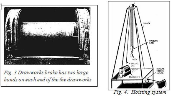
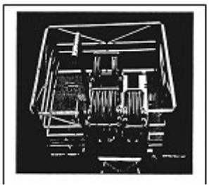
The drawworks is one of the largest and heaviest piece of equipment on a rig. It has a spool-shaped revolving drum around which crew members wrap the wire rope they call drilling line. It also has several shafts, clutches, brakes, and chain-and-gear drives. The shafts, clutches, and drives allow the driller to engage and disengage equipment on the drawworks. The driller can also change the speed with which the drum revolves, thereby varying the speed with which the drawworks raises the traveling block and hook. The driller controls the drawworks from a panel, or console, near the drawworks.
The drawworks also has a heavy-duty main brake. Large bands on both rims of the drum stop the drum from turning when the driller engages the brake. When the brake is disengaged, the drawworks drum lets out drilling line to lower the traveling block. An auxiliary hydraulic or electric brake assists the main brake when the draw-works is raising or lowering heavy loads. The auxiliary brake absorbs some of the momentum created by a heavy load. The main brake
thereby works more efficiently.
A cathead is a winch, or windlass, on which a line, such as rope, cable, or chain, is coiled. When activated, the cathead reels in the line with great force. Pulling on a rope, cable, or chain is vital to screwing and unscrewing (making up and breaking out) drill pipe.
333
A friction cathead is a steel spool a foot (30 centimetres) or so in diameter. It revolves as the catshaft revolves. Crew members used to employ friction catheads and a length of catline—a large-diameter rope made out of plant fiber, or hemp—to move heavy equipment around the rig floor. One floorhand rigged up one end of the catline to the object they wished to move. Another wrapped the other end of the catline a couple of times around the cathead. (Rig hands called this operation "taking wraps around the cathead.") This second crew member gripped the line near the turning cathead and, by pulling hard or not so hard on the line, adjusted the amount of friction the cathead applied to the line. When the crew member tightened the line— applied more friction—on the cathead, the cathead pulled on the catline and lifted the object. When the crew member loosened the catline wraps on the cathead— released the friction—the cathead stopped pulling on the catline.
An automatic cathead also pulls on a wire rope or, in some cases, on a chain, but in a way very different from a friction cathead. Instead of having to manually adjust tension on a line, the driller simply moves a control lever on the console to engage or disengage an automatic cathead. The automatic cathead on the driller's side of the drawworks is the makeup cathead. The automatic cathead on the opposite side of the drawworks is the breakout cathead, which looks exactly like the makeup cathead.
Drilling line is wireline, or wire rope. Drilling line is, however, considerably larger than the wire rope on the tongs. Wire rope is what most of the world calls cable. Wire rope manufacturers make drilling line by braiding several steel wires together. It looks like cloth, or fiber, rope except that it is made from steel wire rather than plant or plastic fibers. Drilling line ranges in diameter from ¾ to 2 inches, or about 22 to 51 millimetres.
First, assume that the derrick is lying horizontally in its cradle in the substructure. The drawworks is on the rig floor and the rig's engines are running. To begin, workers take one end of the rope off the supply reel, which is resting on the ground near the substructure. They pull the line from the reel to the top of the derrick. There the rig builders installed a large set of pulleys, or sheaves, termed the crown block. Crown blocks have several sheaves over which workers string the drilling line. They thread, or reeve, the drilling line over a groove in a crown block sheave. Then they pull the end of the line to another set of sheaves placed near the middle of the derrick. This sheave set is the traveling block.
334
The driller raises and lowers the traveling block in the derrick as drilling progresses. During string-up, however, the traveling block is also stationary until workers complete the string-up job. To continue stringing up, they reeve the end of the drilling line through one of the traveling block sheaves. Then they pull the line back to the crown block. They reeve the line over another sheave in the crown block and pull it back to the traveling block. There, they reeve the line through another traveling block sheave and pull it back to the crown.
The number of times the workers reeve the line through the blocks depends on the weight the line has to support and on the size of the crown and traveling blocks. Crown blocks and traveling blocks vary in the size and the number of sheaves they contain.
After the workers reeve the line for the last time over the crown block sheaves, they pull the end of the line to the drawworks. They secure the end of the drilling line to the drum in the drawworks. A worker then powers up the drawworks and takes several wraps of line around the drum, much as an angler reels in fishing line after a cast. Since the traveling block is resting on a support that holds it stationary, the line runs through it without moving it. The part of the drilling line running from the drawworks to the crown block is the fast line. It moves when the rig is operating. That is, after the drilling crew readies the rig, the fast line moves on or off the drawworks drum when the driller raises or lowers the traveling block.
Fig. 5. Several sheaves make up the crown block.
335
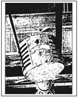
Fig. 6. Travelling block
During the drilling of a well, the drilling line carries many tons of drill pipe and other tools in and out of the hole over a distance of several miles; or it uses many newtons of force moving drill pipe over a distance of thousands of metres. The crew therefore rates drilling line use in ton-miles or megajoules. (When a line has moved 1,000 newtons of load over a distance of 1,000 metres, the line has given i megajoule of service.) The driller keeps careful track of how many ton-miles (megajoules) of wear occur over time. By consulting specially prepared tables, the driller knows when it is time to slip the line. Slipping the line places unworn line on the wear points where the line goes through and over sheaves in the traveling and crown blocks. The drilling line also wears where it spools off the drawworks drum.
(Baker R. “A Primer of Oil Well Drilling”, 2001, Austin, Texas)
336

5. Make collocations from the following words.
1. drawworks |
A. block |
2. auxiliary |
B. line |
3. crown |
C. rope |
4. drilling |
D. drum |
5. makeup |
E. load |
7. heavy |
F. brake |
8. wire |
G. cathead |
6. Fill in the gaps with the most suitable words or terms from the text.
1. Once the last line has been strung over the
sheaves, the end of the line goes down to the drawworks drum, where it is
firmly |
. |
|
|
||
2. |
The |
extra sheave |
is needed for |
|
the deadline. |
3. |
The brake is mounted on the end of the |
. |
|||
4. A typical hoisting system is made up of the drawworks, a mast or derrick,
the crown block, |
|
|
|
, and the wire rope drilling line. |
|||||||
5. |
You can lift an |
|
on |
|
|
|
|
||||
object |
the rig floor wrapping the rope around a |
||||||||||
|
. |
|
|
|
|
|
could be strung. |
|
|
|
|
6. |
For |
heavier loads, twelve or more |
|
|
|
|
|
||||
7. |
The main brake is used for |
|
and |
the |
drawworks |
||||||
drum.
7. Match the words in the left column with the definitions in the right one.
1. drawworks |
A. wedge-shaped pieces of metal with teeth or other |
|
gripping elements that are used to prevent pipe from |
|
slipping down into the hole. |
2. sheave |
B. a wire rope used to support the drilling tools |
3. spool |
C. an assembly of sheaves mounted on beams at the |
|
top of the derrick or mast and over which the |
|
drilling line is reeved. |
4. fastline |
D. it is essentially a large winch that spools off or takes |
|
in the drilling line and thus raises or lowers the bit. |
5. cathead |
E. a cylinder around which wire rope is wound in |
|
the drawworks. |
6. drilling line |
F. the end of the drilling line that is affixed to the |
|
drum or reel of the drawworks. |
|
337 |

7. brake |
G. grooved pulley. |
8. crown block |
H. a device for arresting the motion of a mechanism, |
|
usually by means of friction. |
9. drum |
I. a spool-shaped attachment on the end of the |
|
catshaft, around which rope for hoisting and moving |
|
heavy equipment on or near the rig floor is wound. |
10. bit |
J. the drawworks drum. |
8. Fill in the chart with the functions of the hoisting system components.
Component Composition Function
Drawworks
Crown block
Drilling line
Cathead
9. Lab. Assignment:”Hoisting Equipment”.
|
Terms and Vocabulary |
die |
плашка, оправка |
drill collar |
воротник бура, утяжелённая штанга; |
|
утяжелённая бурильная труба, удлинитель |
drill stem |
бурильная колонна; бурильная штанга |
|
(при роторном бурении); ударная штанга |
drill string |
бурильная колонна |
gooseneck |
S-образное колено трубы |
kelly bushing |
вкладыш под ведущую бурильную трубу |
master bushing |
постоянная втулка |
slips |
клин, шлипс |
tool joint |
бурильный замок |
saver sub |
переводник с перенарезаемой резьбой в |
|
бурильной колонне |
threaded |
с резьбой |
stab (v) |
заводить конец верхней трубы в муфту |
|
нижней |
mate (v) |
соединять |
drive shaft |
приводной вал |
338
10. Read the text “Rotary system components”. Define what is IT in bold in each paragraph using the words from the right column.
Rotary system components
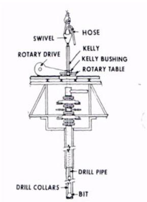
Rotating equipment includes the devices that make the bit turn. On a conventional rig, the equipment consists of a swivel, an upper kelly cock, a special length of pipe called the kelly, a lower kelly cock, a kelly saver sub, the rotary table, the drill pipe, the drill collars, and the bit. Some contractors install a special system on their rigs called a top drive. It replaces many parts of the conventional rotating system; top drives are discussed in more detail later.
According to the American Petroleum Institute (API), all the pipe between the swivel and the bit, including the kelly, the drill pipe, and drill collars, is the drill stem. (The API is a trade association that sets oilfield standards and specifications.) The drill string includes only the drill pipe—not the kelly and the drill collars. Be aware, however, that practically everybody in the oil patch uses "drill string" to mean the drill pipe and the drill collars.
Fig. 7. Schematic of rotary system
339
1. |
|
IT is a remarkable device. IT sustains the weight of the |
|
drill stem, permits it to rotate, and provides a pas- |
|
sageway for drilling mud to get into the drill stem. IT |
Rotary table |
also has a large bail, similar to the bail, or handle, on a |
|
bucket but much, much larger. IT’s bail fits inside the |
|
hook at the bottom of the traveling block. Crew |
|
members also attach the rotary, or kelly, hose to ITs side |
Drilling stem |
at the gooseneck. The gooseneck is a curved piece of |
|
erosion-resistant pipe. Drilling mud enters IT through |
|
the rotary hose and the gooseneck. |
Swivel |
|
|
2. |
|
IT is square or hexagonal, instead of round, because the |
Diesel engine |
flat sides provide a way to make IT turn. The driller |
|
lowers IT inside a corresponding square or hexagonal |
|
openng in the kelly bushing. The kelly bushing fits into |
|
another rotating component called the master bushing. |
Drill string |
The master bushing fits inside the rotary table. Thus, as |
|
the rotary table rotates, the master bushing and the kelly |
|
bushing also rotate. Since the IT mates with the kelly |
|
bushing, IT also rotates. The pipe rotates because the |
Drill bit |
crew connects it to the ITs bottom. Finally, the drill |
|
collars and the bit rotate because the crew connects them |
|
to the drill pipe. |
|
IT passes through the kelly bushing. The master bushing |
Kelly |
rotates the kelly bushing, which rotates IT. The drill |
|
pipe, drill collars, and bit rotate as well. They disappear |
|
into the rotary table where you can't see them. At the |
Hose |
same time, the mud pump sends mud through the rotary |
|
hose and into the swivel. From the swivel, the mud |
|
flows inside and down the kelly, the drill pipe, the drill |
|
collars, and out the bit. The mud shoots out the bit and |
Top drive |
lifts cuttings up the hole to the surface. |
|
|
|
340
3.
The crew fits the master bushing into IT. During normal drilling operations, the master bushing drives the kelly
bushing. When drilling stops and the kelly bushing is Tool joints out of the master bushing, the master bushing can hold
the slips.. Slips have strong, toothlike gripping elements called dies. Slips fit around the drill string and suspend it in the hole. With the drill string suspended by the slips, the crew can remove the kelly and the swivel from the drill string. The traveling block and hook no longer suspend the drill string.
4.
IT hangs from the traveling block's hook in place of a conventional swivel. A powerful heavy-duty motor in IT turns a threaded drive shaft. The crew stabs, or inserts, the unit's drive shaft directly into the top of the drill stem. When the driller starts ITs motor, it rotates the drill stem and the bit. The rig therefore does not use a conventional swivel, a kelly, a rotating rotary table and master bushing, or a kelly bushing. Rigs with IT still need, however, a rotary table and master bushing to provide a place for the slips to suspend the pipe.
5.
IT consists of the drill pipe and special, heavy-walled pipe called drill collars. Manufacturers make IT from steel, but they also use aluminum.
IT is heavier than drill pipe, however. The drilling crew uses them to put weight on the bit to make it drill. They install them in the drill string below the drill pipe. Number of drill collars depends on how much weight the bit needs and on how much the drill collars weigh.
6.
IT is a threaded piece on each end of the pipe . The pipe maker welds IT to the pipe. The crew connects the pipe with IT. IT adds a significant amount of weight to drill pipe, but not enough to make it weigh anywhere near as much as drill collars.
341

7.
Manufacturers make two types of IT for rotary drilling: roller cone and diamond. Roller cone have steel coneshaped devices that roll, or turn, as the bit rotates. Most of them have three cones; some have two and some have four, however. Its makers mill or forge teeth out of the body of the cones, or they insert very hard tungsten carbide buttons into the cones. The teeth or inserted buttons cut, scrape, or gouge the rock as IT rotates.
11. Label each picture with correct rotary system component and describe its composition.
342

343
12.Match the words in the left column with the definitions in the right one. There is one extra definition.
1. swivel |
A. a device similar to a power swivel that is used |
|
in place of the rotary table to turn the drill stem. |
2. kelly |
B. the column of drill pipe with attached tool |
|
joints that transmits fluid and rotational power |
|
from the kelly to the drill collars and the bit. |
3. rotary table |
C. a special device placed around the kelly that |
|
mates with the kelly flats and fits into the master |
|
bushing of the rotary table. |
4. drill stem |
D. a rotary tool that is hung from the rotary hook |
|
and the traveling block to suspend the drill stem |
|
and to permit it to rotate freely. |
5. drill string |
E. seamless steel or aluminum pipe made up in |
|
the drill stem between the kelly or top drive on |
|
the surface and the drill collars on the bottom. |
6. drill bit |
F. a flexible tube for conveying liquids or gases |
|
under pressure |
7. top drive |
G. the principal component of a rotary, or rotary |
|
machine, used to turn the drill stem and support |
|
the drilling assembly. |
8. hose |
H. a heavy, thick-walled tube, usually steel, |
|
placed between the drill pipe and the bit in the |
|
drill stem. |
9. drill pipe |
I. a heavy coupling element for drill pipe. |
10. drill collar |
J. the cutting or boring element used for drilling |
11. kelly bushing |
K. all members in the assembly used for rotary |
|
drilling from the swivel to the bit. |
|
L. the heavy steel tubular device suspended from |
|
the swivel through the rotary table and |
|
connected to the top joint of drill pipe to turn the |
|
drill stem as the rotary table turns. |
344
13. Listen to a top drive system description. Read the questions 1–5 and choose the answer – A,B,C or D – that best suits the information in the text.
1. What rotates the drill string when using a top drive system?
A.Rotary table
B.Drive shaft
C.Guide rails
D.Crew members
2. Which of the following is the advantage of the top drive?
A.It is cheaper to maintain than a rotary table system.
B.It requires less qualification of the driller.
C.It reduces drilling time.
D.It weights lighter that a kelly assembly.
3. According to the text, what helps a top drive system to prevent hole problems?
A.It allows drill string rotation at any hole point due to a wide range of rotating power.
B.It allows moving drilling rigs a short distance.
C.It allows reducing the number of connections of pipes.
D.It allows handling stands of pipes more efficiently.
4.Which of the following was mentioned as a disadvantage of a top drive system?
A. It requires an additional weight on a bit.
B. The drill string should be constantly maintained. C. A drilling line wears faster.
D. It’s difficult to use it in highly deviated holes.
5.Which of the components is NOT included in a top drive system?
A.A rotary hose
B.An integrated swivel
C.A traveling block
D.A kelly
345
14. Lab. assignment: “Rotating Equipment, Mast and Structure”.
|
Terms and Vocabulary |
annulus |
кольцеобразный зазор |
bulk storage |
хранение в резервуаре |
discharge line |
нагнетательный трубопровод, выкидная линия, |
|
напорный трубопровод |
mud pit |
отстойник; приёмная ёмкость для бурового |
|
раствора; амбар для хранения бурового |
|
раствора |
return line |
возвратная линия, канат |
rotary hose |
нагнетательный шланг роторной буровой |
|
установки, соединяющий стояк с вертлюгом |
standpipe |
водозаборная колонна |
suction line |
всасывающая линия, приёмная линия (насоса), |
|
всасывающий трубопровод (бурового насоса), |
|
впускной трубопровод |
15. Read the text “Circulating system” and do the exercises.
Circulating System
Mud circulates through many pieces of equipment, including the mud pump, the discharge line, the standpipe, the rotary hose, the swivel, the kelly (or the top drive), the drill pipe, the drill collars, the drill bit, the annulus, the return line, the shale shaker, the desilter, the desander, the mud pits, and the suction line.
The mud pump draws in mud through a suction line from the mud pits, or tanks, and sends it out a discharge line. From the discharge line, the mud goes into the standpipe. The standpipe runs vertically up one leg of the derrick. Mud exits the standpipe into a strong, flexible, and reinforced rubber hose called the rotary hose, or kelly hose. The rotary hose joins the swivel at the gooseneck. The mud then flows down the kelly (or through the top drive), drill pipe, and drill collars. It jets out of the bit nozzles and moves cuttings away from the bit. The mud and cuttings then head up the hole in the annulus. The annulus, or annular space, is the area between the drill string and the wall of the hole.
346

Fig. 8. Schematic of example rig circulating system
The mud leaves the annulus through a steel pipe called the mud return line. It falls over a vibrating screen, the shale shaker. The shaker screens out the larger cuttings and, in some cases, dump them into the reserve pit. Offshore and in environmentally sensitive areas, however, the shaker dumps the cuttings into a receptacle. Later, the contractor removes the receptacle, washes the cuttings if required, and properly disposes of them. In either case, the clean mud drains back into the mud tanks. The pump then recycles it back down the hole. The mud pump recirculates the mud over and over throughout
347

the drilling of the well. From time to time, the derrickhand adds water, clay, and other materials to make up for downhole losses. This crew member also adjusts the mud's properties as the borehole encounters new and different formations.
16. Define whether the following sentences are true (T) or false (F).
T / F |
1. Having flowed through the swivel, mud flows down the top drive. |
|
T / F |
2. |
Shaker screens always dump the cuttings into the reserve pits. |
T / F |
3. |
Mud is drained into the mud tanks. |
T / F |
4. |
Mud is circulated during the drilling of the well. |
T / F |
5. |
The mud properties are changed according to various formation |
17. Put the following circulating system components in the right order to make the system work.
Shale shaker |
Mud |
Drill bit |
Discharge line |
|
pump |
|
|
Desander |
Centrifugal pump |
Standpipe |
Suction line |
Drill pipe |
Swivel |
Kelly hose |
Earthen pits |
Degasser |
Desilter |
Annulus |
18. Listen to the text and mark the statement with T if it is true and with
F if it is false.
1.Crew members prepare the mud in mud tanks.
2.Usually a drill rig uses two pumps operating simulatneously.
3.The mud going through the rotary hose carries cuttings with it.
4.Nozzles are special holes in the bit through which the mud jets out and removes cuttings away.
5.The last piece of equipment the mud goes through before returning back into the mud tank and closing the circulation cycle is a shale shaker.
348

19.Lab. assignment:” Mud circulations and treating equipment”.
20.Analyzing the failures, define what drilling rig components are broken and what must be done.
Drilling mud is full |
Mud doesn’t flow |
The drill pipe and |
of solids, |
out of the |
attached bit don’t |
particles, and |
standpipe |
rotate |
gas |
|
|
Drilling lines being strung between the travelling and the crown blocks are jammed
The drawworks and |
A square kelly |
The drill string |
|
mud pumps don’t |
doesn’t fit the |
can not be raised |
|
run |
opening in the kelly |
||
|
|||
|
drive bushing |
|
21. You are going to have panel discussion on the following topic – “Drill Bits Chew Rock Formation”. It will consist of two parts:
1.Video “ Sophisticated Bit technology”
2.Presentations “ Bit Technology Development”
|
WORDLIST |
ENGLISH |
RUSSIAN |
accumulator unit |
аккумулятор |
annulus |
кольцеобразный зазор |
automatic cathead |
автоматическая шпилевая катушка |
auxiliary |
вспомогательный, дополнительный |
backup tongs |
удерживающий ключ для труб |
blowout preventer |
противовыбросовое устройство, превентор |
brake |
тормоз |
bulk storage |
хранение в резервуаре |
casing |
крепление скважины обсадными трубами |
cathead |
шпилевая катушка |
catline |
канат для работ со шпилевой катушкой |
centrifuge |
центрифуга, центрифугировать, очищать |
|
(буровой раствор) на центрифуге |
choke manifold |
штуцерный манифольд (противовыбросового |
|
оборудования) |
|
349 |
circulation system |
система промывки |
clutch |
муфта, соединять |
console |
пульт управления |
convential |
стандартный |
crown block |
кронблок |
degasser |
устройство для дегазирования бурового |
|
раствора, дегазатор |
derrick |
буровая вышка |
desander |
пескоотделитель (устройство для очистки |
|
бурового раствора от песка) |
desilter |
ситогидроциклонный илоотделитель |
deviation |
отклонение |
die |
плашка, оправка |
discharge line |
нагнетательный трубопровод, выкидная |
|
линия, напорный трубопровод |
doghouse |
будка для переодевания рабочей вахты (на |
|
буровой), будка бурового мастера |
drawworks |
буровая лебедка |
drill collar |
воротник бура, утяжелённая штанга; |
|
утяжелённая бурильная труба, удлинитель |
drill stem |
бурильная колонна; бурильная штанга (при |
|
роторном бурении); ударная штанга |
drill string |
бурильная колонна |
driller’s console |
пульт управления бурильщика |
drilling line |
буровой канат, рабочий канат |
elevators |
элеватор |
fast line |
ходовой конец (талевого каната) |
friction cathead |
фрикционная шпилевая катушка |
gooseneck |
S-образное колено трубы |
grid |
батарея, энергетическая система |
hook |
крюк |
kelly bushing |
вкладыш под ведущую бурильную трубу |
makeup cathead, breakout |
шпилевая катушка для свинчивания |
cathead |
бурильных труб |
master bushing |
постоянная втулка |
mud pit |
отстойник; приёмная ёмкость для бурового |
|
раствора; амбар для хранения бурового |
|
раствора |
pipe rack |
стеллаж для труб |
reeve |
оснащать (талевую систему), продевать |
|
350 |
|
канат (через блок), надевать (на шкив) |
return line |
возвратная линия, канат |
rotary hose |
нагнетательный шланг роторной буровой |
|
установки, соединяющий стояк с вертлюгом |
shaft |
вал, ось, шток |
sheave |
шкив; блок; ролик, каротажный ролик, |
|
колесо с желобчатым ободом |
slant rig |
наклонная буровая установка |
slip |
скольжение, травить канат |
slips |
клин для захвата буровых и обсадных труб, |
|
шлипс |
spool |
шпулька, бобина |
standpipe |
водозаборная колонна |
suction line |
всасывающая линия, приёмная линия |
|
(насоса), всасывающий трубопровод |
|
(бурового насоса), впускной трубопровод |
tool joint |
бурильный замок |
torque converters |
гидротрансформатор |
winch |
лебедка |
hopper |
бункер, засыпная воронка, приёмный жёлоб, |
|
загрузочный ковш |
kelly |
«квадрат», ведущая труба |
kellybushing |
втулка квадрата |
mast |
вышка мачтового типа |
masterbushing |
основной вкладыш ротора |
mechanical system |
механический привод |
monkeyboard |
люлька верхового рабочего; полати для |
|
верхового рабочего; площадка для верхового |
|
рабочего |
mousehole |
шурф для двухтрубки |
mud pit |
отстойник, приёмная ёмкость для бурового |
|
раствора, амбар для хранения бурового |
|
раствора |
mud return line |
линия для выхода бурового раствора |
mud-gas separator |
газосепаратор для бурового раствора |
pipe rack |
приспособление для укладки бурильных |
|
труб в штабель (в вышке), мостки для труб |
|
(на буровой), стеллаж для труб |
pipe ramp |
горизонтальные мостки для труб |
power system |
энергосистема |
|
351 |
rathole |
шурф для квадрата |
|
|
rotary hose |
буровой шланг |
|
|
rotating system |
система вращения |
|
|
shale-shaker |
вибрационное сито |
|
|
substructure |
подвышечное |
основание; |
фундамент; |
|
фундаментная рама (буровой мачты) |
||
swivel |
вертлюг |
|
|
traveling block |
талевый блок |
|
|
wire rope |
проволочный трос |
|
|
weight indicator |
индикатор нагрузки на буровой инструмент |
||
352
UNIT 5
CASING. CEMENTING
It is generally not possible to drill a well through all of the formations from surface to the target depth in one hole section. The well is therefore drilled in sections, with each section of the well being sealed of by lining the inside of the borehole with steel pipes, known as casing and filling the annular space between this casing string and the borehole with cement, before drilling the subsequent hole section.
Lead-in
Make comments about reasons for casing off formations.
unstable formation |
high pore pressure |
zones |
|
|
Casing off |
well formation |
lost circulation |
zone |
|
selective access |
structural support |
1. Pay special attention to the pronunciation and stress of the following
words. |
|
conduit [΄kondjuıt, ΄konduıt] |
threaded anticipated liner |
subsequent [΄sλbsıkwənt] |
hydraulically |
2. Read the following texts and match them with casing types.
Casing types: 1. Conductor casing; 2. Surface casing; 3. Intermediate casing; 4. Production casing; 5. Liner
353

a)
It either runs through the pay zone or sets just above the pay zone. The main function of this casing is to isolate the production interval from other formations. It also provides protection for the environment in the event of failure of the tubing string during production operations and permits the production tubing to be replaced or repaired later in the life of the well.
c)
It is a short casing string which is suspended from the inside of the previous casing string by a special device known as ......... This device is attached to the top joint of the casing in the string. The collar and slips support its weight. The overlap with the previous casing is usually 200ft. –
e)
A heavy, flanged steel fitting connected to the first string of casing. It provides a housing for slips and packing assemblies, allows suspension of intermediate and production strings of casing, and supplies the means for the annulus to be sealed off.
b)
It generally sets at approximately 1000-1500ft. below the ground level. The main functions: prevents cave-in of unconsolidated, weaker, nearsurface sediments and protects the shallow fresh water sands from contamination; supports and protects from corrosion any subsequent casing strings run in the well; supports the wellhead and BOP equipment (in case of kick, surface casing generally allows
d)
It is the largest casing. It is generally set at approximately 100ft, below the ground level. Its function is to seal off unconsolidated formations shallow depths. It protects the subsequent casing strings from corrosion and may be used to support structurally some of the wellhead load.
f)
It is used to isolate troublesome formations including unstable shales, lost circulation zones, abnormally pressured zones and squeezing salts. When abnormal formation pore pressures are present in the deeper portions of a well, this casing is needed to protect formations from the pressures created by the required high-drilling-fluid density.
354
4.Underline the components or functions that are correct.
1.Casing is a strong
a) lead pipe |
b) steel pipe |
c) the entire length of all the |
joints |
|
|
2. Casing protects the shallow zones from |
|
|
a) being contaminated |
b) caving in |
c) being flooded |
3. Intermediate casing is needed for
a) pressure stabilization b) production interval isolation c) wellhead support
4. |
Liner consists of |
|
|
a) joints and collars |
b) catches and slips |
c) collars and slips |
|
5. |
Production casing |
|
|
a) |
can be replaced |
b) can be repaired |
c) protect environment |
6. |
Conductor casing has |
|
|
a) the largest diameter |
b) the widest walls |
c) the smallest diameter |
|
5. Listen to the description of the well completion process. Then read the statements and choose the alternative – A, B, C or D – that best suits the information in the text.
1.To complete the oil or gas well A. a production casing is used. B. a surface casing is used.
C. a conductor casing is used.
D. an intermediate casing is used.
2.Primary recovery means that hydrocarbons are forced up to the surface due
to
A. primary pressure B. secondary pressure C. air pressure
D. natural pressure
3.Even the field is developed professionally,
356

A.nine per cent of gas and forty five per cent of oil remain behind.
B.ninety per cent of gas and forty five per cent of oil remain behind.
C.fifteen per cent of gas and fifty four per cent of oil remain behind.
D.fifty per cent of gas and fourteen per cent of oil remain behind.
4. The Christmas tree is
A.a wellbottom area fitted with attractive drill bits.
B.a wellhead area fitted with surface casing.
C.a wellbottom area fitted with downhole pumps and valves.
D.a wellhead area fitted with many valves and pipes.
5.It is possible for a well to make a stand up to A. five kilometers from the production platform.
B. five kilometers from the nearest pipe connection. C. as many kilometers as necessary.
D. five kilometers from the wellhead.
6.Read the text “Eight Steps Ensure Successful Cement Jobs”. Define eight factors the operators must consider for successful cementing jobs.
Drilling mud condition cement composition selection
proper cementing system selection spacer and flush use
the casing centralization pressure optimization the pipe move
displacement rate maximization proper temperature slurry design
1. Drilling mud condition
This factor is the most important in achieving good displacement during a cement job. The following measures are necessary to follow:
•determine the hole volume that can be circulated; evaluate the % of wellbore that is actually being circulated ( for best results, use a caliper or material balance to determine downhole fluid mobility and check for annular fluid that is not moving);
•circulate the drilling mud to help break the gel structure of the fluid; condition the drilling mud until equilibrium is achieved (after casing is on bottom and before the displacement begins,
357

circulating the mud decreases its viscosity and increases mobility);
•never allow the drilling mud to set static for extended periods, especially at elevated temperatures. (mud properties coming out of the well are the same as the mud pumped in); continue circulating until displacement program begins;
•modify the flow properties of the drilling fluid to optimize mobility and drilling cuttings removal;
•examine the mud gel strength profile during the job planning stage and just before the cement job (an optimum drilling fluid will have flat, non progressive gel strengths);
•measure the gel strength development during the job planning stage, at downhole temperature and pressure.
2.
They separate the dissimilar drilling mud from the cement. Also they enhance gelled-mud removal and allow better cement bond with the borehole. They are designed to serve various needs: (1) help well control; (2) provide increased mud-removal benefits. The following guidelines should be considered to achieve maximum mud displacement:
•pump the spacer fluid at an optimized rate or as fast as possible without breaking down the formation;
•provide spacer contact time and volume to remove the greatest possible amount of mud;
•make sure the viscosity, yield point and density of both the spacer and the cement slurry, are at least the same as the drilling fluid;
•design the spacer package to water-wet the surface of the pipe and formation thoroughly when using oil-based or synthetic – based drilling fluids.
Flushes are used for thinning and dispersing drilling – fluid particles. These fluids go into turbulence at low rates, helping to clean drilling fluid from the annulus.
358

3.
•rotating and reciprocating casing before and during cementing breaks up stationary, gelled pockets of drilling mud;
•loosens cuttings trapped the gelled mud;
•allows high displacement efficiency at lower pump rates by keeping the drilling mud flowing.
4.
It helps to optimize drilling –fluid displacement. Good pipe standoff helps ensure uniform flow patterns around the casing. Equalizing the friction loss or force that flowing cement exerts around the annular clearance increases drilling-fluid removal. The best mud displacement at optimum rate is achieved when annular clearance is 1–1.5 in. Pipe movement and displacement are severely restricted. Centralizers and other mechanical cementing aids commonly used in the industry, also serve as inline laminar flow mixers. They change flow patterns and promote better mud displacement and removal.
5.
•high-energy flow in the annulus is most effective to ensure good mud displacement;
•turbulent flow around the full casing circumference is desirable, but not absolutely essential;
•when turbulent flow is not a viable option for the formation or wellbore configuration, the highest pump rate is feasible;
•the best cementing results are obtained when the spacer and cement are pumped at maximum energy, the spacer is appropriately designed to remove mud and good competent cement is used.
6.
One can optimize cost and displacement efficiency by following guidelines:
•design the job on basis of actual wellbore circulating temperatures;
•estimate the bottomhole circulating temperature (BHCT) using the API;
•use the actual downhole temperatures measured;
•include surface mixing time when estimating job time.
359

7.
Operators are encouraged to design cement slurry for its specific application, with good properties to allow placement in a normal time period. The ideal cement slurry has no measurable, free water, provides adequate retarder to ensure proper placement and maintains stable density to ensure hydrostatic control. Several criteria affect slurry design:
•well depth
•BHCT
•Bottomhole static temperature (BHST)
•Drilling fluid hydrostatic pressure
•Drilling fluid type
•Slurry density
•Lost circulation
•Gas migration potential
•Pumping time
• Quality of mix water |
fluid-loss control |
•Flow regime
•Quality of cement
•Dry or liquid additives
•Strength development
•Quality of the cement testing laboratory and equipment.
8.
These systems vary in their capability to provide good zone isolation in changing environments. The traditional approach to cement selection has been on the basis that higher compressive strengths result in higher cement sheath quality. One of the most versatile systems to apply is foam cement, which produces a more ductile and resilient cement and withstands the stress associated with casing expansion and contraction.
(Oil &Gas Journal, 1999)
7. Match the two parts of the sentences.
1. |
Low annular clearance |
A. real bottomhole temperature |
|
|
analysis. |
2. |
Drilling mud flow properties are |
B. the turbulent flow is required. |
3. |
Displacement efficiency can be |
C. equal the cement slurry density |
achieved by |
and yield point as well. |
|
4. |
Drilling fluid density and yield point |
D. define the slurry composition. |
|
360 |
|
5. |
Flow patterns can be changed by |
E. influences mud displacement. |
6. |
For displacement rate increase |
F. mechanical cementing |
|
|
technologies application. |
7. |
Pumping time can |
G. in proportion to drilling |
|
|
cuttings removal rate. |
8. Look through the text once again and fill in the chart.
Steps |
Objective |
Description |
Priority |
drilling mud condition
cement composition selection
proper cementing system selection
spacer and flush use
the casing centralization
the pipe move
displacement rate maximization
proper temperature slurry design
9. You have some money for drilling procedure improvement in the certain oilfield. Unfortunately, the sum is not great and you are to choose four steps for successful cementing jobs. Moderate the whole implementation procedure and be ready to prove your choice.
|
WORDLIST |
|
|
ENGLISH |
RUSSIAN |
annular clearance |
затрубный интервал |
annular space |
затрубное пространство |
anticipated load |
ожидаемая нагрузка |
bond (bonding) |
соединение |
BOP (blowout |
противовыбросовое устройство, |
preventer) |
противовыбросовый превентор |
|
361 |
bottomhole circulation |
динамическая температура на забое |
temperature (BHCT) |
|
bottomhole static |
статическая температура на забое |
temperature (BHST) |
|
casing circumference |
окружность обсадных труб |
casing failure |
разрушение обсадных труб |
casing hanger |
клиновой захват для спуска обсадных труб |
casing head pressure |
давление на устье скважины |
casing string |
колонна обсадных труб |
cement sheath |
фильтрационная корка на стенках скважины |
centralizer |
центратордля центрирования колонн |
|
обсадных труб |
compatibility |
совместимость |
compressive strength |
предел прочности при сжатии |
conductor casing |
направляющая труба (первая колонна обсадных |
|
труб, спускаемая в буровую скважину на |
|
сравнительно небольшую глубину для |
|
придания скважине правильного направления и |
|
перекрытия и пород, склонных к осыпанию) |
conduit |
трубопровод |
contact time |
время контакта |
contaminate |
загрязнять |
contraction |
сжатие |
disperse |
диспергировать |
displacement rate |
объемный расход |
downhole (bottomhole) |
забойное давление |
drill cuttings |
шлам |
drilling fluid |
буровой раствор (промывочная буровая |
|
жидкость) |
ductile |
пластичный вязкий |
elevated temperature |
надземная \ поверхностная температура |
equivalent circulating |
эквивалент циркуляционной плотности |
density (ЕCD) |
|
expansion |
расширение |
flow path |
пути проникновения потока |
flow pattern |
структура потока |
fluid mobility |
подвижность жидкости |
fluid removal |
смещение жидкости (отвод жидкости) |
flush(es) |
струя жидкости |
foam cement |
цементная пена |
|
362 |
friction loss |
потери на трении |
gelled mud |
густой буровой раствор |
guide shoe (casing shoe) |
башмак обсадных труб (деталь из твердой |
|
стали, прикрепляемая к нижней трубе |
|
обсадной колонны, имеющая острый край для |
|
срезания грунта) |
hole volume |
объем скважины |
inclination |
угол наклона буровой скважины к горизонту |
intermediate casing |
промежуточная обсадная колонна |
|
(техническая) |
laminar flow |
ламинарное течение |
liner hanger |
подвеска обсадной колонны хвостовика |
pay zone |
зона с промышленной нефтегазоносностью |
production casing |
эксплутационная колонна |
production interval |
продуктивный интервал |
reciprocating |
расхаживание труб |
resilient |
упругий \ эластичный |
retarder |
замедлитель реакции \ демпфер |
set time |
установленное время |
setting |
установка; спуск и посадка обсадных труб |
setting depth |
глубина установки |
slip |
клин, плашка |
slurry |
цементный раствор |
spacer(s) |
промежуточное кольцо (жидкость с высокой |
|
вязкостью и плотностью для удаления |
|
бурового раствора) |
standoff |
степень центрирования (обсадной колонны в |
|
стволе) |
surface casing |
колонна обсадных труб после кондуктора |
|
(кондуктор) |
surface string |
комплект противовыбросовых превенторов |
surge pressure |
гидравлический удар (давление) |
swab (pressure) |
поршень для откачки из скважины |
thickening time |
время загустевания цементного раствора |
threaded connection |
pезьбовое соединение |
water wet |
смачиваемость |
weighted spacer |
утяжелитель |
yield point |
предел текучести |
363
APPENDIX
SELF-ASSIGNMENT TOPICS
1.Sophisticated bits-characteristics and classification
2.Drilling fluid
3.Underbalance drilling
4.Centralizers
5.Horizontal –direction drilling
6.Vertical drilling
7.Side tracking
8.AutoTrack
9.Modernization of downhole turbine motors
10.Completion (types)
11.Completion components
12.Perforation 13. Stimulation 14.Sand control 15. Workovers
16.Environment protection
17.Support –and-alignment mechanisms
18.Piston pumps
19.Turbodrilling
364
REFERENCES
1.Dictionary for the Petroleum Industry. Austin, Texas: Schlumberger
1997.
2.JP Journal: 2004–2007.
3.Oil and Gas Journal: 1999–2005.
4.Petroleum Engineering Handbook. Society of Petroleum Engineers.
(1992). Richardson, TX, USA.
5.Baker, R. (1994). Primer of Oilwell Drilling. Basic Text of Oil and
Gas Drilling. Houston, Texas.
6.Wood’s Illustrated English – Russian \ Russian-English Petroleum
Technology Dictionary. ALBION WOODS.
7.Белоусов В. Нефтегазовая промышленность: Основные
процессы и англо-русская терминология. – М.: ООО Техинпут,
2006.
8.Булатов В.В., Пальчиков В.В. Англо-русский словарь по нефти и
газу. – М.: Руссо, 2001.
INTERNET RESOURCES
9.www.en.wikipedia.org
10.www.bakerhughes.com
365
Chapter 4
PIPELINE ENGINEERING
R.N. Abramova
Т.V. Vasilchenko
UNIT 1
PIPELINE CONSTRUCTION
Pipeline transport is a transportation of goods through a pipe. Most commonly, liquid and gases are sent, but pneumatic tubes that transport solid capsules using compressed air have also been used.
As for gases and liquids, any chemically stable substance can be sent through a pipeline. Therefore, sewage, slurry, water, or even beer pipelines exist; but the most important are those transporting oil and natural gas.
Lead-in
Fill in the spider gram with the words associated with Pipeline Engineering.
Pipeline
Engineering
Explain your associations.
366
|
Terms and Vocabulary |
gathering system |
система нефтесбора |
pump station |
насосная станция |
crude trunkline |
магистральный трубопровод |
crude tank farm |
резервуарный парк / нефтебаза |
tanker |
танкер |
marine (port) terminal |
портовая нефтебаза |
refinery |
НПЗ – нефтеперерабатывающий завод |
petrochemical plant |
нефтехимический завод |
product line |
продуктопровод |
processing |
переработка |
distribution center |
распределительная база |
oil tankage |
нефтехранилище |
destination |
пункт назначения |
gathering |
сбор |
individual lease |
арендованный нефтяной участок |
moving |
перемещение |
transporting |
доставка |
supply |
запас |
point |
пункт |
distributing |
распределение |
1. Pronounce the following words. Pay special attention to the letters in bold.
lease individual terminal supply variety tankage crude
2. Read the following word formations and learn their pronunciation. Pay special attention to the stress.
distribute – distributing – distribution |
deliver – delivering – delivery |
process – processing |
transport – transporting – |
|
transportation |
produce – product – production |
refine – refinery |
locate – location |
gather – gathering |
367
3. Read the mini-text “Pipeline System”. Look at the diagram and pay attention to the underlined terms in the text.
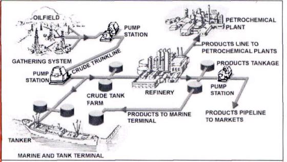
Pipeline System
Fig. 1. Pipeline system
In the petroleum industry, pipelines are used for a variety of purposes:
1.gathering crude oil from individual leases and delivering it to a central location for processing;
2.transporting crude oil from fields to port terminals for tanker transportation;
3.moving crude oil from processing centers and supply points to the refineries and other markets;
4.moving gas from fields to gas processing plants and from these plants to markets;
5.distributing petroleum products from the refineries to the distribution centers.
(http://www.Wikipedia)
368
4. Match English terms with Russian ones. Example: 13. destination – A. пункт назначения
1. |
gathering system |
A. |
распределительная база |
2. |
pump station |
B. |
промышленный трубопровод |
3. |
crude trunkline |
C. |
портовая нефтебаза |
4. |
crude tank farm |
D. |
магистральный трубопровод |
5. |
tanker |
E. |
система нефтесбора |
6. |
marine terminal |
F. |
нефтехранилище |
7. |
refinery |
G. |
распределительная база |
8. |
petrochemical plant |
H. |
нефтехимический завод |
9. |
product line |
I. |
резервуарный парк / нефтебаза |
10. |
processing |
J. |
танкер |
11. |
distribution center |
K. |
НПЗ – нефтеперерабатывающий |
|
|
|
завод |
12. |
oil tankage |
L. |
насосная станция |
13. |
destination |
M. |
переработка |
5. Give the explanation to the following purposes of the pipeline system.
Example: Moving is gas progresses from the gas field to gas processing plants and from there to the market.
•Gathering is …
•Transporting is …
•Moving is …
•Distributing is …
•Gathering system is …
369
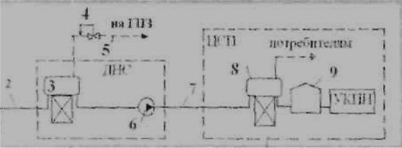
6. Here is the diagram of Russian pipeline gathering system. Use the abovementioned terms and give a short explanation to each element of the pipeline system. (Note the differences).
Fig. 2. Pipeline system |
|
Terms and Vocabulary |
|
line pipe |
труба |
pig trap |
камера приема и пуска средства |
|
очистки и диагностики |
block valve station |
аварийный клапан для отключения |
ESD (emergency shut-down |
аварийный клапан для временного |
valve) |
прекращения (предохранительный |
|
клапан) |
slug catcher |
ловушка для конденсата |
cathodic protection system |
система катодной защиты |
pressure protection system |
система защиты от избыточного |
|
давления |
telemetry system |
система телеметрии, телемеханика |
leak detection system |
система определения утечек |
corrosion resistant |
коррозионно-устойчивый |
line |
трубопровод |
slug |
пробка |
receiving station |
приёмная станция |
backup |
резервное устройство |
coating |
изоляция |
remote operation |
дистанционное управление |
carbon steel |
сталь |
resistant |
нержавеющий |
|
370 |
alloy |
сплав |
loading |
загрузка |
launching |
запуск |
receiving |
прием |
retrieval |
извлечение |
release |
выпуск |
leak |
утечка |
rupture |
порыв, образование трещин |
shut down |
временное прекращение |
emergency |
авария |
allowable pressure |
допустимое давление |
monitoring |
текущий контроль |
7. Pronounce the following words. Pay special attention to the letters in bold.
alloy |
rupture |
corrosion |
release |
launching |
valve |
retrieval |
emergency |
fluid |
automatic |
phase |
ensure |
exceed |
surface |
warn |
|
8. Read the following word formations and learn their pronunciation. Pay special attention to the stress.
resist – resistance – resistant |
permit – permission |
disrupt – disruption |
occur – occurring – occurrence(s) |
install – installation |
allow – allowing – allowable – |
|
allowance |
371

9. You are going to learn some vocabulary to help you understand the text. Study the following dictionary entries, paying attention to specific term definitions. Match the term with the appropriate meaning.
1.disrupt (v) A. afford opportunity or possibility for
2.install (v) B. go beyond the limits of
3.prevent (v) C. interrupt the progress, movement or procedure of
4.ensure (v) D. notify or make aware in advance of something
5.exceed (v) E. connect or set in position and prepare for use
6.permit (v) F. make sure / certain
7.warn (v) G. keep from doing something
10. Read the text “Pipeline Components”. Look at the diagram and pay attention to the underlined terms in the text.
Fig. 3. Components of a pipeline
A pipeline system is comprised of the following components:
1. line pipe – the main component of every pipeline and is usually metallic (carbon steel / corrosion resistant alloy);
2.pig traps – allow safe loading, launching, receiving and retrieval of pigs without disrupting the fluid in the pipelines;
3.block valve stations – isolate section of the pipeline and limit the release of line contents in case of a leak or pipeline rupture;
4.emergency shut-down valves (ESD) – located at both ends of the
pipeline and enable automatic shut down of the line in case of an emergency; 5. slug catcher – installed at the end of a multi-phase pipeline to prevent slugs and to ensure a constant gas flow into the receiving station;
372
6.cathodic protection system – installed as a backup to the external coating to prevent corrosion of the external surface of the pipelines;
7.pressure protection system – protects a pipeline when the line pressure exceeds) the max. allowable pressure;
8.telemetry system – permits pipeline monitoring and remote operation from
a central location;
9.leak detection system – installed to warn that a leak occurred.
11.Match the terms with their functions.
Example: pressure protection system – protects a pipeline when the line pressure exceeds the max. allowable pressure;
1. |
emergency shut-down |
A. |
installed to warn that a leak occurred |
|
valves (ESD) |
|
|
2. |
cathodic protection |
B. |
main component of every pipeline |
|
system |
|
|
3. |
line pipe |
C. |
isolate section of the pipeline and limit |
|
|
|
the release of line contents in case of a |
|
|
|
leak or pipeline rupture |
4. |
slug catcher |
D. |
prevent corrosion of the external surface |
|
|
|
of the pipelines |
5. |
pig traps |
E. |
allow safe loading, launching, receiving |
|
|
|
and retrieval of pigs without disrupting |
|
|
|
the fluid in the pipelines |
6. |
telemetry system |
F. |
prevent slugs and to ensure a constant gas |
|
|
|
flow into the receiving station; |
7. |
block valve stations |
G. |
permits pipeline monitoring and remote |
|
|
|
operation from a central location; |
8. |
leak detection system |
H. |
enable automatic shut down of the line in |
|
|
|
case of an emergency |
12. Give Russian equivalents to the following terms.
Example: rupture – порыв, образование трещин
1. |
corrosion resistant |
13. |
permit |
2. |
launching |
14. |
coating |
3. |
retrieval |
15. |
allowable pressure |
4. |
receiving |
16. |
exceed |
|
|
373 |
|

5. |
loading |
17. |
monitoring |
6. |
disrupt(ing) |
18. |
remote operation |
7. |
shut down |
19. |
warn |
8. |
emergency |
20. |
install |
9. |
leak |
21. |
line pipe |
10. |
slug |
22. |
pipeline |
11. |
backup |
23. |
steel |
12. |
alloy |
24. |
prevent |
13. Pipeline networks are composed of several pieces of equipment that operate together to move products from location to location. The main elements that conform a pipeline system can be summarized as follows:
Initial Injection Station (Supply or Inlet station), Compressor / Pump Stations, Partial Delivery Station (Intermediate Stations), Block Valve Station, Regulator Station and Final Delivery Station (Outlet stations).
Describe the pipeline schematically.
Example: Initial Injection Station – known also as Supply or Inlet station, is basically the beginning of the system, this is where the product is injected into the line. Storage facilities, such as tank terminals, as well as other devices to push the product through the line, like pumps or compressor are usually located at these locations.
Fig. 4. Pipeline components
14. Solve the following situations.
Example: Questions: What are slugs? What do slugs in a multi-phase pipeline prevent?
Answer: the accumulation of a liquid (water, oil or condensate) in a pipeline. Slugs prevent or slow down the flow of fluids in a pipeline.
374