

Chapter 2 - Microcontroller PIC16F84
2.7 Free timer TMR0
Timers are ordinarily most complicated parts of a microcontroller, so it is necessary to set aside more time for their mastering. With their application it is possible to create relations between a real dimension such as "time" and a variable which represents status of a timer within a microcontroller. Physically, timer is a register whose value is continually increasing to 255, and then it starts all over again: 0, 1, 2, 3, 4...255.....1, 2, 3......etc.
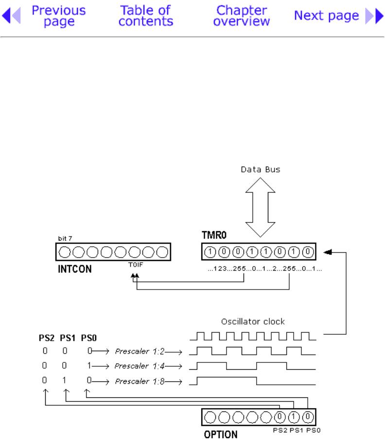
Relation between the timer TMR0 and prescaler
http://www.mikroelektronika.co.yu/english/books/2_08Poglavlje.htm (1 of 6) [30/12/2001 16:53:43]
Chapter 2 - Microcontroller PIC16F84
This incrementing is done in the background of everything a microcontroller does. It is up to programmer to "think up a way" how he will take advantage of this characteristic for his needs. One of the ways is increasing some variable on each timer overflow. If we know how much time a timer needs to make one complete round, then multiplying the value of a variable by that time will yield the total amount of elapsed time.
PIC16F84 has an 8-bit timer. Number of bits determines what value timer counts to before starting to count from zero again. In the case of an 8-bit timer, that number is 256. A simplified scheme of relation between a timer and a prescaler is represented on the previous diagram. Prescaler is a name for the part of a microcontroller which divides oscillator clock before it will reach logic that increases timer status. Number which divides a clock is defined through first three bits in OPTION register. The highest divisor is 256. This actually means that only at every 256th clock, timer status would increase by one. This provides us with the ability to measure longer timer periods.
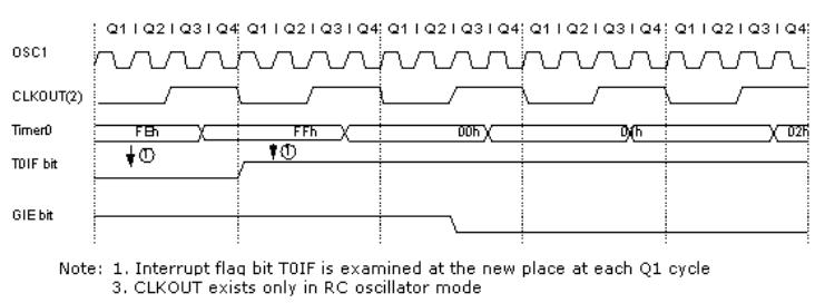
Time diagram of interrupt occurence with TMR0 timer
After each count up to 255, timer resets its value to zero and starts with a new cycle of counting to 255. During each transition from 255 to zero, T0IF bit in INTCOM register is set. If interrupts are allowed to occur, this can be taken advantage of in generating interrupts and in processing interrupt routine. It is up to programmer to reset T0IF bit in interrupt routine, so that new interrupt, or new overflow could be detected. Beside the internal oscillator clock, timer status can also be increased by the external clock on RA4/TOCKI pin. Choosing one of these two options is done in OPTION register through T0CS bit. If this option of external clock is selected, it is possible to define the edge of a signal (rising or falling), on which timer will increase its value.
http://www.mikroelektronika.co.yu/english/books/2_08Poglavlje.htm (2 of 6) [30/12/2001 16:53:43]
Chapter 2 - Microcontroller PIC16F84
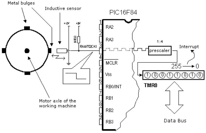
Application of TMR0 timer to determining a number of full axle turns of the working machine of a motor
In practice, one of the typical examples that is solved via external clock and a timer is counting full turns of an axle of some production machine, like transformer winder for instance. Let's wind four metal screws on the axle of a winder. These four screws will represent metal convexity. Let's place now the inductive sensor at a distance of 5mm from the head of a screw. Inductive sensor will generate the falling signal every time the head of the screw is parallel with sensor head. Each signal will represent one fourth of a full turn, and the sum of all full turns will be found in TMR0 timer. Program can easily read this data from the timer through a data bus.
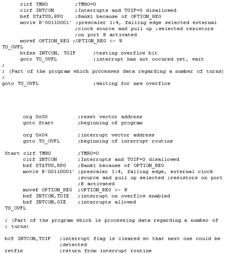
The following example illustrates how to initialize timer to signal falling edges from external clock source with a prescaler 1:4. Timer works in "polig" mode.
http://www.mikroelektronika.co.yu/english/books/2_08Poglavlje.htm (3 of 6) [30/12/2001 16:53:43]
Chapter 2 - Microcontroller PIC16F84
The same example can be realized through an interrupt in the following way:
Prescaler can join either timer TMR0 or a watchdog. Watchdog is a mechanism which microcontroller uses to defend itself against programs getting stuck. As with any other electrical circuit, so with a microcontroller too can occur failure, or some work impairment. Unfortunately,
http://www.mikroelektronika.co.yu/english/books/2_08Poglavlje.htm (4 of 6) [30/12/2001 16:53:43]
Chapter 2 - Microcontroller PIC16F84
microcontroller also has a component called program where problems can occur as well. When this happens, microcontroller will stop working and will remain in that state until someone resets it. Because of this, watchdog mechanism has been introduced. After a certain period of time, watchdog resets the microcontroller (microcontroller in fact resets itself). Watchdog works on a simple principle: if timer overflow occurs, microcontroller is reset, and it starts executing a program all over again. In this way, reset will occur in case of both correct and incorrect functioning. Next step is preventing reset in case of correct functioning, which is done by writing zero in WDT register (instruction CLRWDT) every time it nears its overflow. Thus program will prevent a reset as long as it's executing correctly. Once it gets stuck, zero will be written, overflow of WDT timer and a reset will occur which will bring the microcontroller back to correct functioning again.
Prescaler is accorded to timer TMR0, or to watchdog timer with the help of PSA bit in OPTION register. By clearing PSA bit, prescaler will be accorded to timer TMR0. When prescaler is accorded to timer TMR0, all instructions of writing to TMR0 register (CLRF TMR0, MOVWF TMR0, BSF TMR0,...) will clear prescaler. When prescaler is assigned to a watchdog timer, only CLRWDT instruction will clear a prescaler at the same time watchdog clears it. Prescaler change is completely under programmer's control, and can be changed while program is running.
There is only one prescaler and one timer. Depending on the needs, they are accorded either to timer TMR0 or to a watchdog.
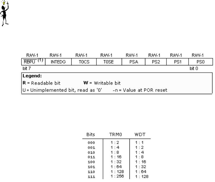
OPTION Control Register
Bit 0:2 PS0, PS1, PS2 (Prescaler Rate Select bit)
The subject of a prescaler, and how these bits affect the work of a microcontroller will be covered in section on TMR0.
http://www.mikroelektronika.co.yu/english/books/2_08Poglavlje.htm (5 of 6) [30/12/2001 16:53:43]

Chapter 2 - Microcontroller PIC16F84
bit 3 PSA (Prescaler Assignment bit)
Bit which assigns prescaler between TMR0 and watchdog timer. 1=prescaler is assigned to watchdog timer.
0=prescaler is assigned to free timer TMR0
bit 4 T0SE (TMR0 Source Edge Select bit)
If we are able to trigger TMR0 with impulses from a RA4/T0CKI pin, this bit will determine whether it will be on the rising or falling edge of a signal.
1=falling edge 0=rising edge
bit 5 T0CS (TMR0 Clock Source Select bit)
This pin enables a free timer to increment its status either from an internal oscillator, which is on every 1 of oscillator clock, or via external impulses on RA4/T0CKI pin.
1=external impulses 0=1/4 internal clock
bit 6 INTEDG (Interrupt Edge Select bit)
If occurrence of interrupts is enabled, this bit will determine at what edge interrupt on RB0/INT pin will occur.
1= "pull-up" resistors turned off 0= "pull-up" resistors turned on
bit 7 RBPU (PORTB Pull-up Enable bit)
This bit turns internal pull-up resistors on port B on or off. 1='pull-up' resistors turned on
0='pull-up' resistors turned off
© Copyright 1999. mikroElektronika. All Rights Reserved. For any comments contact webmaster.
http://www.mikroelektronika.co.yu/english/books/2_08Poglavlje.htm (6 of 6) [30/12/2001 16:53:43]