


Chapter 2 - Microcontroller PIC16F84
2.1 Clock generator - oscillator
Oscillator circuit is used for providing a microcontroller with a clock. Clock is needed so that microcontroller could execute a program or program instructions.
Types of oscillators
PIC16F84 can work with four different configurations of an oscillator. Since configurations with crystal oscillator and resistor-condenser (RC) are the ones that are used most frequently, these are the only ones we will mention here. Microcontroller type with a crystal oscillator has in its designation XT, and a microcontroller with resistor-condenser pair has a designation RC. This is important because you need to mention the type of oscillator when buying a microcontroller.
XT Oscillator
Crystal oscillator is kept in metal housing with two pins where you have written down the frequency at which crystal oscillates. One ceramic condenser of 30pF whose other end is connected to the mass needs to be connected with each pin.
Oscillator and condensers can be packed in joint housing with three pins. Such element is called ceramic resonator and is represented in charts like the one below. Center pins of the element is the mass, while end pins are connected with OSC1 and OSC2 pins on the microcontroller. When designing a device, the rule is to place an oscillator nearer a microcontroller, so as to avoid any interference on lines on which microcontroller is receiving a clock.
Connecting the quartz oscillator to give clock to a microcontroller
Connecting a resonator onto a microcontroller
RC Oscillator
http://www.mikroelektronika.co.yu/english/books/2_02Poglavlje.htm (1 of 3) [30/12/2001 16:53:30]
Chapter 2 - Microcontroller PIC16F84
In applications where great time precision is not necessary, RC oscillator offers additional savings during purchase. Resonant frequency of RC oscillator depends on supply voltage rate, resistance R, capacity C and working temperature. It should be mentioned here that resonant frequency is also influenced by normal variations in process parameters, by tolerance of external R and C components, etc.
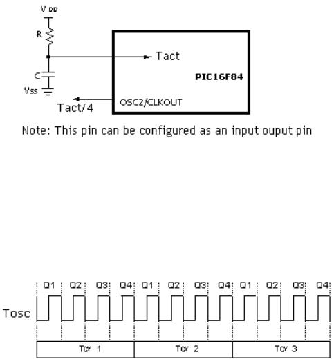
Above diagram shows how RC oscillator is connected with PIC16F84. With value of resistor R being below 2.2k, oscillator can become unstable, or it can even stop the oscillation. With very high value of R (ex.1M) oscillator becomes very sensitive to noise and humidity. It is recommended that value of resistor R should be between 3 and 100k. Even though oscillator will work without an external condenser (C=0pF), condenser above 20pF should still be used for noise and stability. No matter which oscillator is being used, in order to get a clock that microcontroller works upon, a clock of the oscillator must be divided by 4. Oscillator clock divided by 4 can also be obtained on OSC2/CLKOUT pin, and can be used for testing or synchronizing other logical circuits.
Relationship between a clock and a number of instruction cycles
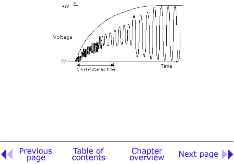
Following a supply, oscillator starts oscillating. Oscillation at first has an uneven period and amplitude, but after some period of time it becomes stabilized.
http://www.mikroelektronika.co.yu/english/books/2_02Poglavlje.htm (2 of 3) [30/12/2001 16:53:30]
Chapter 2 - Microcontroller PIC16F84
Signal of an oscillator clock after receiving the supply on the microcontroller
To prevent such inaccurate clock from influencing microcontroller's performance, we need to keep the microcontroller in reset state during stabilization of oscillator's clock. Above diagram shows a typical shape of a signal which microcontroller gets from the quartz oscillator following a supply.
© Copyright 1999. mikroElektronika. All Rights Reserved. For any comments contact webmaster.
http://www.mikroelektronika.co.yu/english/books/2_02Poglavlje.htm (3 of 3) [30/12/2001 16:53:30]

Chapter 2 - Microcontroller PIC16F84
Chapter 2 - Microcontroller PIC16F84
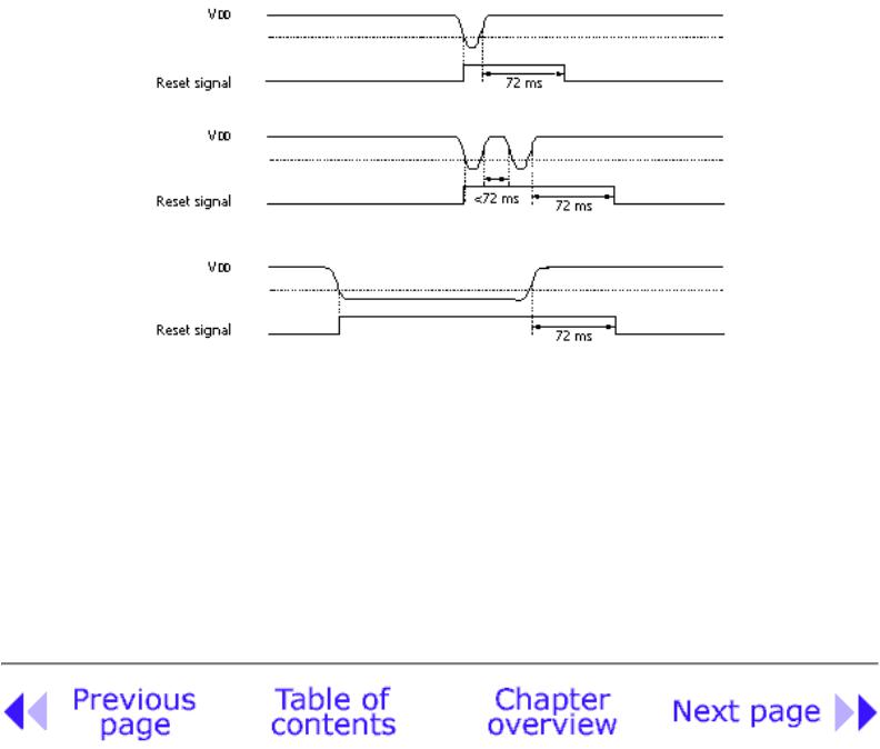
Impulse for resetting during supply (power-up) is generated by microcontroller itself when it detects an increase in supply Vdd (in a range from 1.2V to 1.8V). That impulse lasts 72ms which is enough time for an oscillator to get stabilized. These 72ms are provided by an internal PWRT timer which has its own RC oscillator. Microcontroller is in a reset mode as long as PWRT is active. However, as device is working, problem arises when supply doesn't drop to zero but falls below the limit that guarantees microcontroller's proper functioning. This is a likely case in practice, especially in industrial environment where disturbances and instability of supply are an everyday occurrence. To solve this problem we need to make sure that microcontroller is in a reset state each time supply falls below the approved limit.
Examples of supply drop below the limit
If, according to electrical specification, internal reset circuit of a microcontroller can not satisfy the needs, special electronic components can be used which are capable of generating the desired reset signal. Beside this function, they can also function in watching over supply voltage. If voltage drops below specified level, a logical zero appears on MCLR pin which holds the microcontroller in reset state until voltage is not within limits that guarantee correct performance.
© Copyright 1999. mikroElektronika. All Rights Reserved. For any comments contact webmaster.
http://www.mikroelektronika.co.yu/english/books/2_03Poglavlje.htm (2 of 2) [30/12/2001 16:53:31]