

Chapter 6 - Samples
Seven-Segment Display (multiplexing)
The segments in a 7-segment display are arranged to form a single digit from 0 to 9 as shown in the animation:
We can display a multi-digit number by connecting additional displays. Even though LCD displays are more comfortable to work with, 7-segment displays are still standard in the industry. This is due to their temperature robustness, visibility and wide viewing angle. Segments are marked with non-capital letters: a, b, c, d, e, f, g and dp, where dp is the decimal period.
The 8 LEDs inside each display can be arranged with a common cathode or common anode. With a common cathode display, the common cathode must be connected to the 0v rail and the LEDs are turned on with a logic one. Common anode displays must have the common anode connected to the +5v rail. The segments are turned on with a logic zero.
The size of a display is measured in millimeters, the height of the digit itself (not the housing, but the digit!). Displays are available with a digit height of 7,10, 13.5, 20, or 25 millimeters. They come in different colors, including: red, orange, and green.
The simplest way to drive a display is via a display driver. These are available for up to 4 displays.
Alternatively displays can be driven by a microcontroller and if more than one display is required, the method of driving them is called "multiplexing."
The main difference between the two methods is the number of "drive lines." A special driver may need only a single "clock" line and the driver chip will access all the segments and increment the display.
If a single display is to be driven from a microcontroller, 7 lines will be needed plus one for the decimal point. For each additional display, only one extra line is needed.
To produce a 4, 5 or 6 digit display, all the 7-segment displays are connected in parallel.
The common line (the common-cathode line) is taken out separately and this line is taken low for a short period of time to turn on the display.
Each display is turned on in turn and if this is repeated at a rate above 100 times per second, it will appear that all the displays are on at the same time.
As each display is turned on, the appropriate information must be delivered to it so that it will give the correct reading.
Up to 6 displays can be accessed like this without the brightness of each display being affected. Each display is turned on very hard for one-sixth the time and the POV (persistence of vision) of
http://www.mikroelektronika.co.yu/english/books/6_09Poglavlje.htm (1 of 6) [30/12/2001 16:54:37]
Chapter 6 - Samples
our eye thinks the display is turned on the whole time.
All the timing signals for the display are produced by the program, the advantage of a microcontroller driving the display is flexibility.
The display can be configured as an up-counter, down-counter, and can produce a number of messages using letters of the alphabet that can be readily displayed.
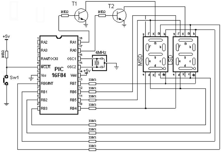
The example below shows how to dive two displays.
Connecting a microcontroller to 7-segment displays in multiplex mode
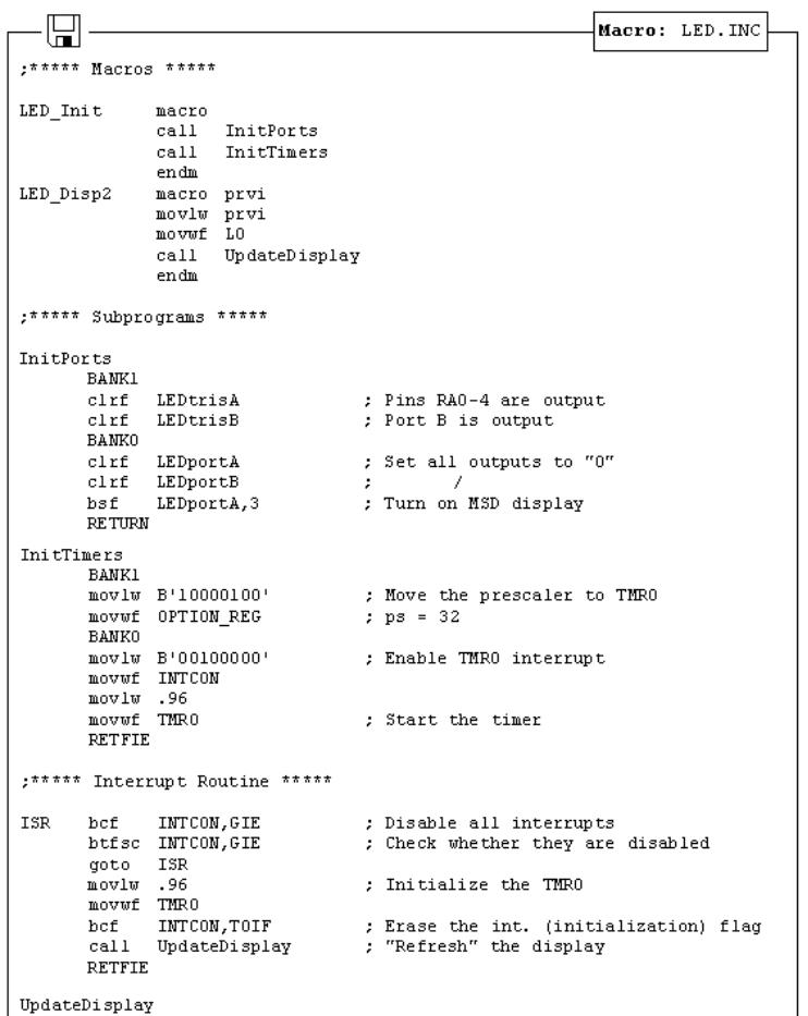
File Led.inc contains two macros: LED_Init and LED_Disp2. The first macro is used for display initialization. That is where display refreshment period is defined as well as microcontroller pins used for connecting the displays. The second macro is used for displaying numbers from 0 to 99 on two displays.
Macro LED_Disp2 has one argument:
LED_Disp2 first macro
first is the number from 0 to 99 to be displayed on Msd and Lsd digit.
Example: LED_Disp12 0x34
Number 34 will be shown on the display
http://www.mikroelektronika.co.yu/english/books/6_09Poglavlje.htm (2 of 6) [30/12/2001 16:54:37]
Chapter 6 - Samples
Realization of a macro is given in the following listing.
http://www.mikroelektronika.co.yu/english/books/6_09Poglavlje.htm (3 of 6) [30/12/2001 16:54:37]
Chapter 6 - Samples
http://www.mikroelektronika.co.yu/english/books/6_09Poglavlje.htm (4 of 6) [30/12/2001 16:54:37]
Chapter 6 - Samples
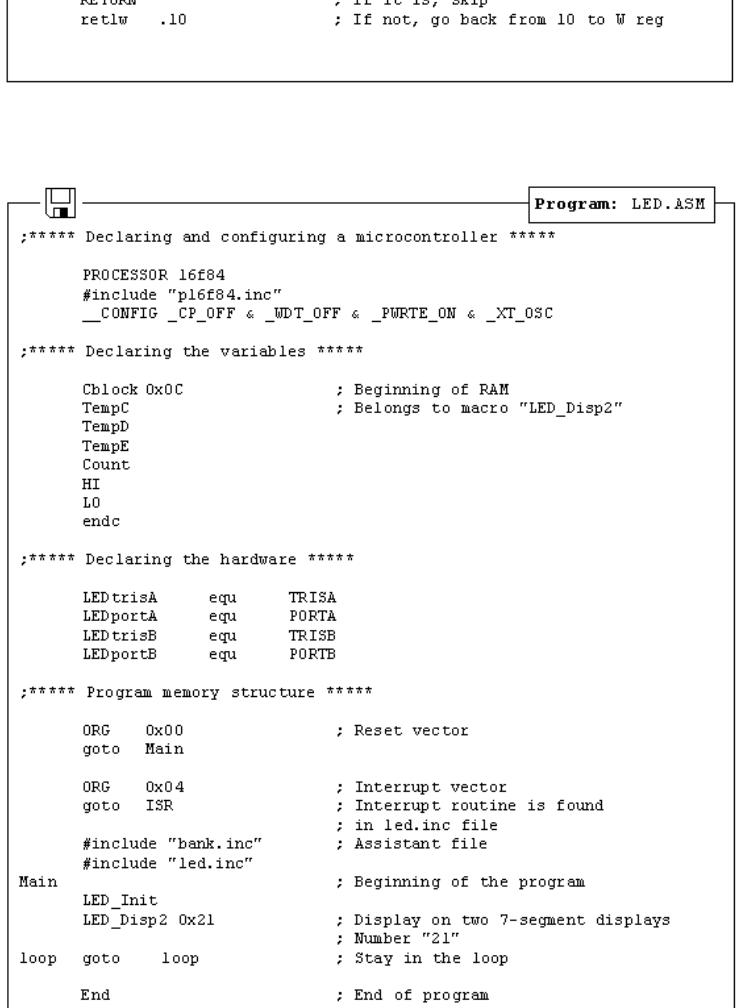
The following example shows the use of macros in a program. Program displays number '21' in two 7-segment digits.
http://www.mikroelektronika.co.yu/english/books/6_09Poglavlje.htm (5 of 6) [30/12/2001 16:54:37]
Chapter 6 - Samples
© Copyright 1999. mikroElektronika. All Rights Reserved. For any comments contact webmaster.
http://www.mikroelektronika.co.yu/english/books/6_09Poglavlje.htm (6 of 6) [30/12/2001 16:54:37]