

Chapter 6 - Samples
LCD Display
More microcontroller devices are using 'smart |
|
LCD' displays to output visual information. The |
|
following discussion covers the connection of a |
|
Hitachi LCD display to a PIC microcontroller. |
|
LCD displays designed around Hitachi's LCD |
|
HD44780 module, are inexpensive, easy to use, |
|
and it is even possible to produce a readout |
|
using the 8 x 80 pixels of the display. Hitachi |
|
LCD displays have a standard ASCII set of |
|
characters plus Japanese, Greek and |
A 16x2 line Hitachi HD44780 display |
mathematical symbols. |
Each of the 640 pixels of the display must be accessed individually and this is done with a number of surface-mount driver/controller chips mounted on the back of the display. This saves an enormous amount of wiring and controlling so that only a few lines are required to access the display to the outside world. We can communicate to the display via an 8-bit data bus or 4-bit data bus.
For a 8-bit data bus, the display requires a +5v supply plus 11 I/O lines. For a 4-bit data bus it only requires the supply lines plus seven extra lines. When the LCD display is not enabled, data lines are tri-state which means they are in a state of high impedance (as though they are disconnected) and this means they do not interfere with the operation of the microcontroller when the display is not being addressed.
The LCD also requires 3 "control" lines from the microcontroller.
The Enable (E) line allows access to the display through R/W and RS lines. When this line is low, the LCD is disabled and ignores signals from R/W and RS. When (E) line is high, the LCD checks the state of the two control lines and responds accordingly.
The Read.Write (R/W) line determines the direction of data between the LCD and microcontroller. When it is low, data is written to the LCD. When it is high, data is read from the LCD.
With the help of the Register select (RS) line, the LCD interprets the type of data on data lines. When it is low, an instruction is being written to the LCD. When it is high, a character is being written to the LCD.
Logic status on control lines:
E0 Access to LCD disabled
1 Access to LCD enabled
R/W 0 Writing data to LCD
http://www.mikroelektronika.co.yu/english/books/6_10Poglavlje.htm (1 of 13) [30/12/2001 16:54:44]
Chapter 6 - Samples
1 Reading data from LCD
RS 0 Instruction
1 Character
Writing data to the LCD is done in several steps:
Set R/W bit to low
Set RS bit to logic 0 or 1 (instruction or character)
Set data to data lines (if it is writing)
Set E line to high
Set E line to low
Read data from data lines (if it is reading)
Reading data from the LCD is done in the same way, but control line R/W has to be high. When we send a high to the LCD, it will reset and wait for instructions. Typical instructions sent to LCD display after a reset are: turning on a display, turning on a cursor and writing characters from left to right.
When the LCD is initialized, it is ready to continue receiving data or instructions. If it receives a character, it will write it on the display and move the cursor one space to the right. The Cursor marks the next location where a character will be written. When we want to write a series of characters, first we need to set up the starting address, and then send one character at a time. Characters that can be shown on the display are stored in data display (DD) RAM. The size of DDRAM is 80 bytes.
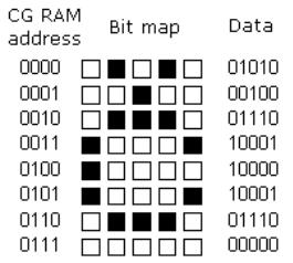
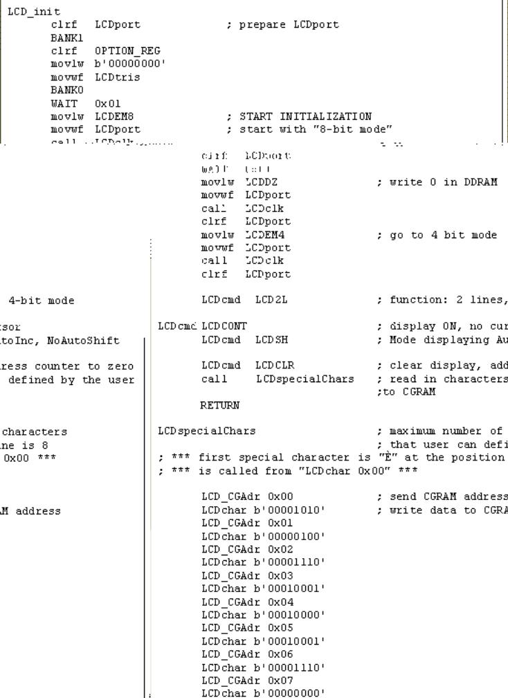
The LCD display also possesses 64 bytes of CharacterGenerator (CG) RAM. This memory is used for characters defined by the user. Data in CG RAM is represented as an 8- bit character bit-map.
Each character takes up 8 bytes of CG RAM, so the total number of characters, which the user can define is eight. In order to read in the character bit-map to the LCD display, we must first set the CG RAM address to starting point (usually 0), and then write data to the display. The definition of a 'special' character is given in the picture opposite.
Before we access DD RAM after defining a special character, the program must set the DD RAM address. Writing and reading data from any LCD memory is done from the last address which was set up using set-address instruction. Once the address of DD RAM is set, a new written character will be displayed at the appropriate place on the screen.
Until now we discussed the operation of writing and reading to an LCD as if it were an ordinary memory. But this is not so. The LCD controller needs 40 to 120 microseconds (uS) for writing and reading. Other operations can take up to 5 mS. During that time, the microcontroller can not access the LCD, so a program needs to know when the LCD is busy. We can solve this in two ways.
http://www.mikroelektronika.co.yu/english/books/6_10Poglavlje.htm (2 of 13) [30/12/2001 16:54:44]
Chapter 6 - Samples
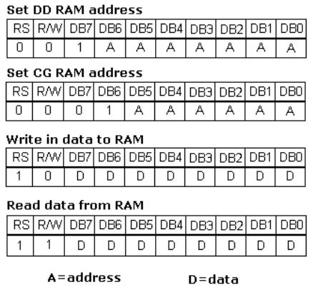
One way is to check the BUSY bit found on data line D7. This is not the best method because LCD's can get stuck, and program will then stay forever in a loop checking the BUSY bit. The other way is to introduce a delay in the program. The delay has to be long enough for the LCD to finish the operation in process. Instructions for writing to and reading from an LCD memory are shown in the previous table.
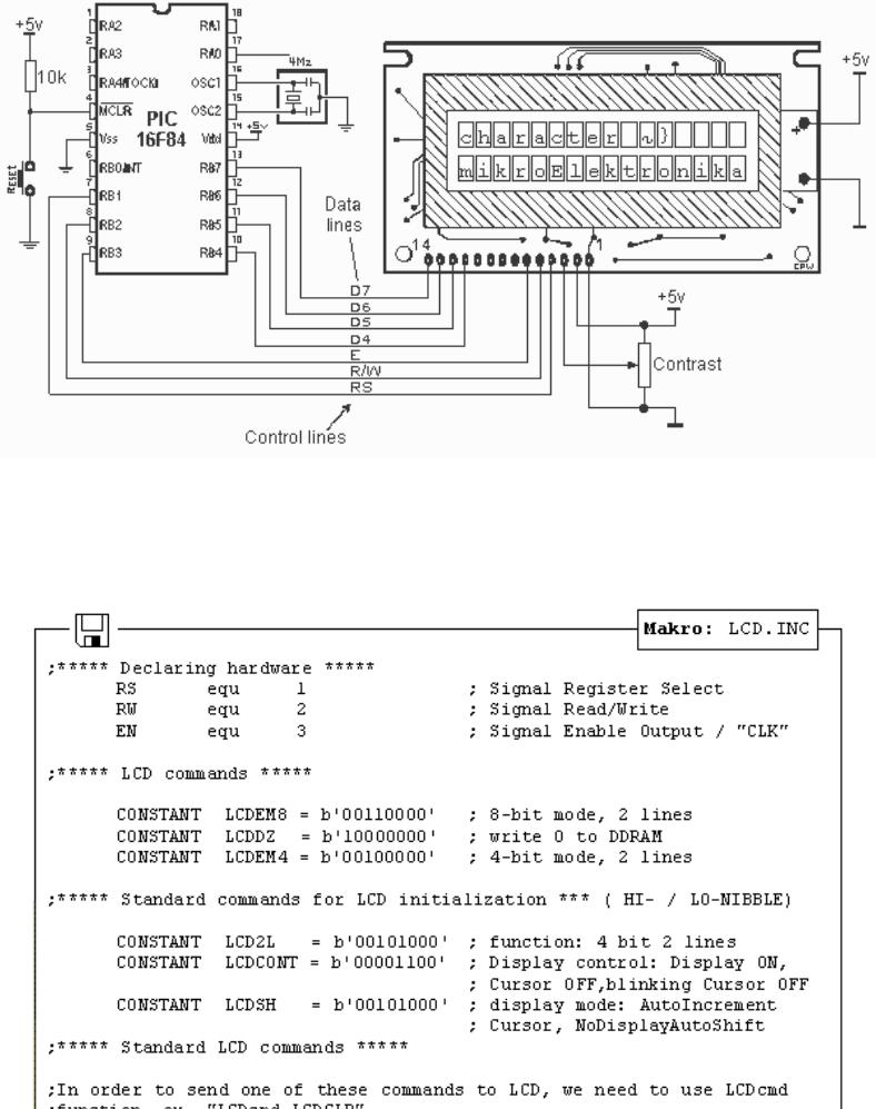
At the beginning we mentioned that we needed 11 I/O lines to communicate with an LCD. However, we can communicate with an LCD through a 4-bit data bus. Thus we can reduce the total number of communication lines to seven. The wiring for connection via a 4-bit data bus is shown in the diagram below. In this example we use an LCD display with 2x16 characters, labelled LM16X212 by Japanese maker SHARP. The message 'character' is written in the first row: and two special characters '~' and '}' are displayed. In the second row we have produced the word 'mikroElektronika'.
http://www.mikroelektronika.co.yu/english/books/6_10Poglavlje.htm (3 of 13) [30/12/2001 16:54:44]
Chapter 6 - Samples
Connecting an LCD display to a microcontroller
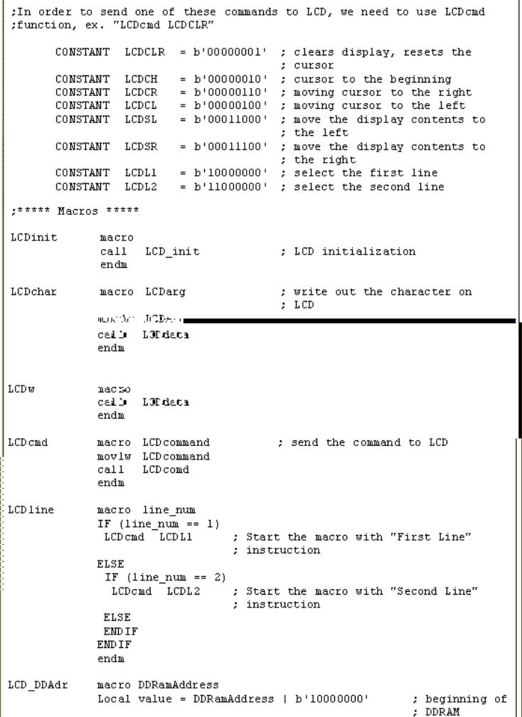
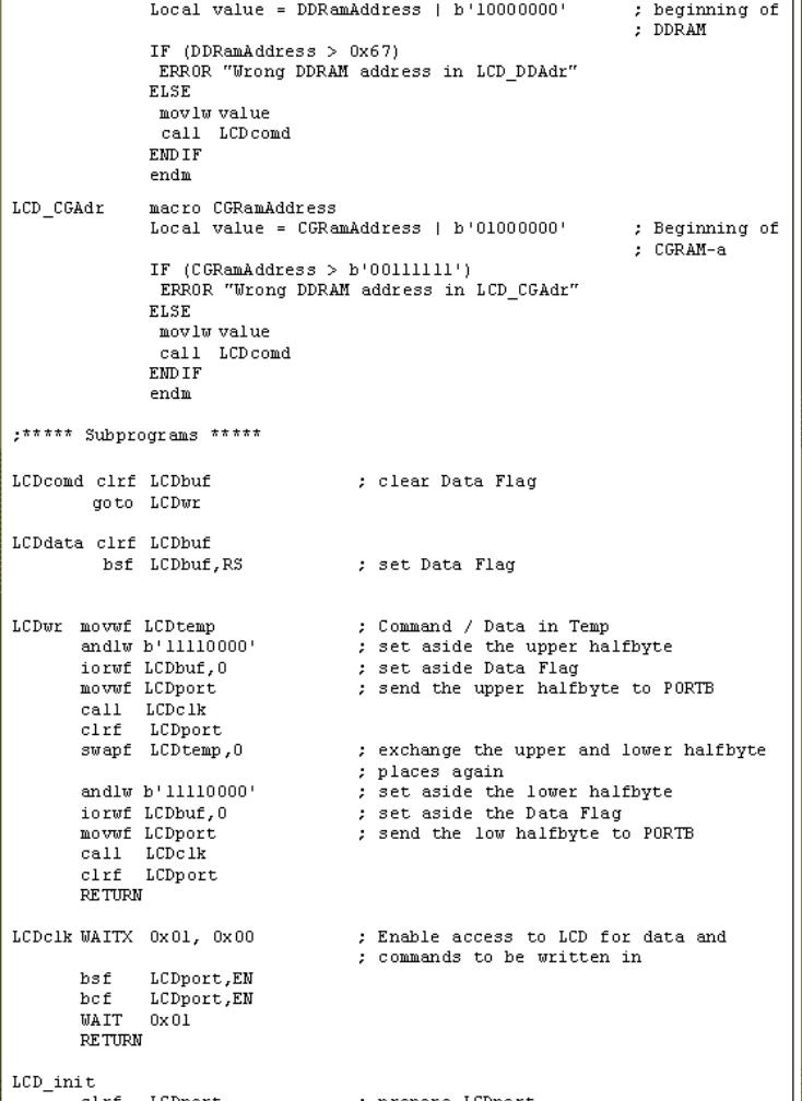
File LCD.inc contains a group of macros for use when working with LCD displays.
http://www.mikroelektronika.co.yu/english/books/6_10Poglavlje.htm (4 of 13) [30/12/2001 16:54:44]
Chapter 6 - Samples
http://www.mikroelektronika.co.yu/english/books/6_10Poglavlje.htm (5 of 13) [30/12/2001 16:54:44]
Chapter 6 - Samples
http://www.mikroelektronika.co.yu/english/books/6_10Poglavlje.htm (6 of 13) [30/12/2001 16:54:44]
Chapter 6 - Samples
http://www.mikroelektronika.co.yu/english/books/6_10Poglavlje.htm (7 of 13) [30/12/2001 16:54:44]
Chapter 6 - Samples
Macro Terms
LCDinit macro used to initialize LCD. Initialize port for LCD. LCD is configured to work in four-bit mode.
Example: LCDinit
LCDchar LCDarg Write ASCII character. Argument is ASCII sign.
Example: LCDChar 'd'
LCDw Write character found in W register.
Example: movlw 'p'
LCDw
LCDcmd LCDcommand Sending command instructions
Example: LCDcmd LCDCH
LCD_DDAdr DDRamAddress Set DD RAM address.
Example: LCD_DDAdr .3
LCDline line_num Set cursor to the beginning of 1st or 2nd row
Example: LCDline 2
http://www.mikroelektronika.co.yu/english/books/6_10Poglavlje.htm (8 of 13) [30/12/2001 16:54:44]
Chapter 6 - Samples
When working with a microcontroller the numbers are presented in a binary form.
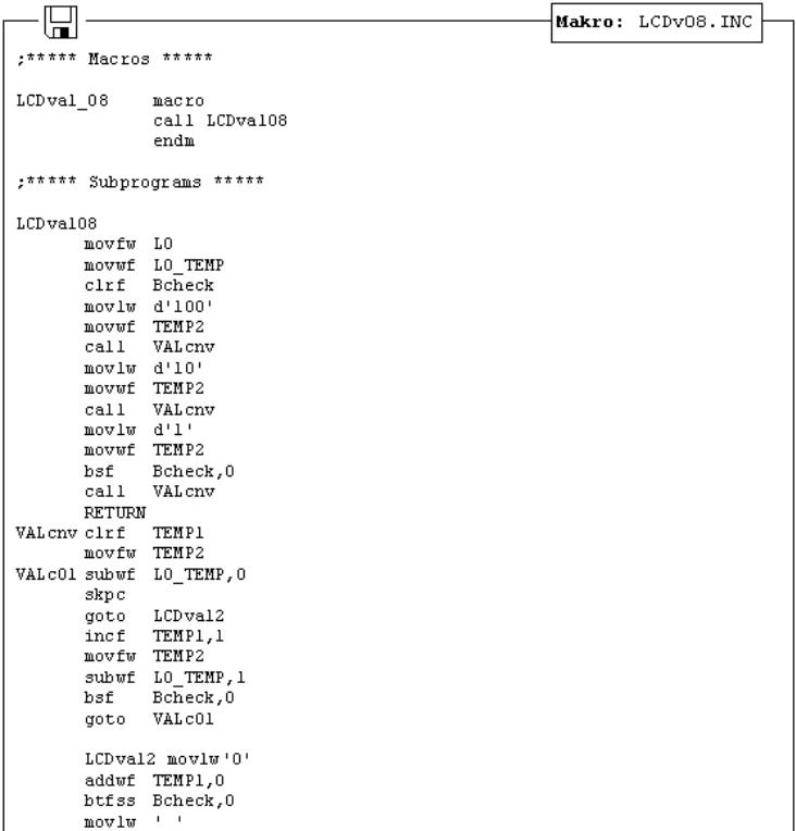
As such, they cannot be displayed on a display. That's why it is necessary to change the numbers from a binary system into a decimal system so they can be easily understood. Listings of two macros LCDva1_08 and LCDva1_16 are given below. The first converts a number from the binary system to the decimal system and displays it on an LCD display.
Macro LCDval_08 converts an eight-bit binary number into a decimal number from 0 to 255 and displays it on the LCD display. It is necessary to declare the following variables in the main program: TEMP1, TEMP2, LO, LO_TEMP, Bcheck. An eight-bit binary number is found in variable LO. When a macro is executed, the decimal equivalent of its number will be displayed on the LCD display. The leading zeros before the number will not be displayed.
http://www.mikroelektronika.co.yu/english/books/6_10Poglavlje.htm (9 of 13) [30/12/2001 16:54:44]
Chapter 6 - Samples
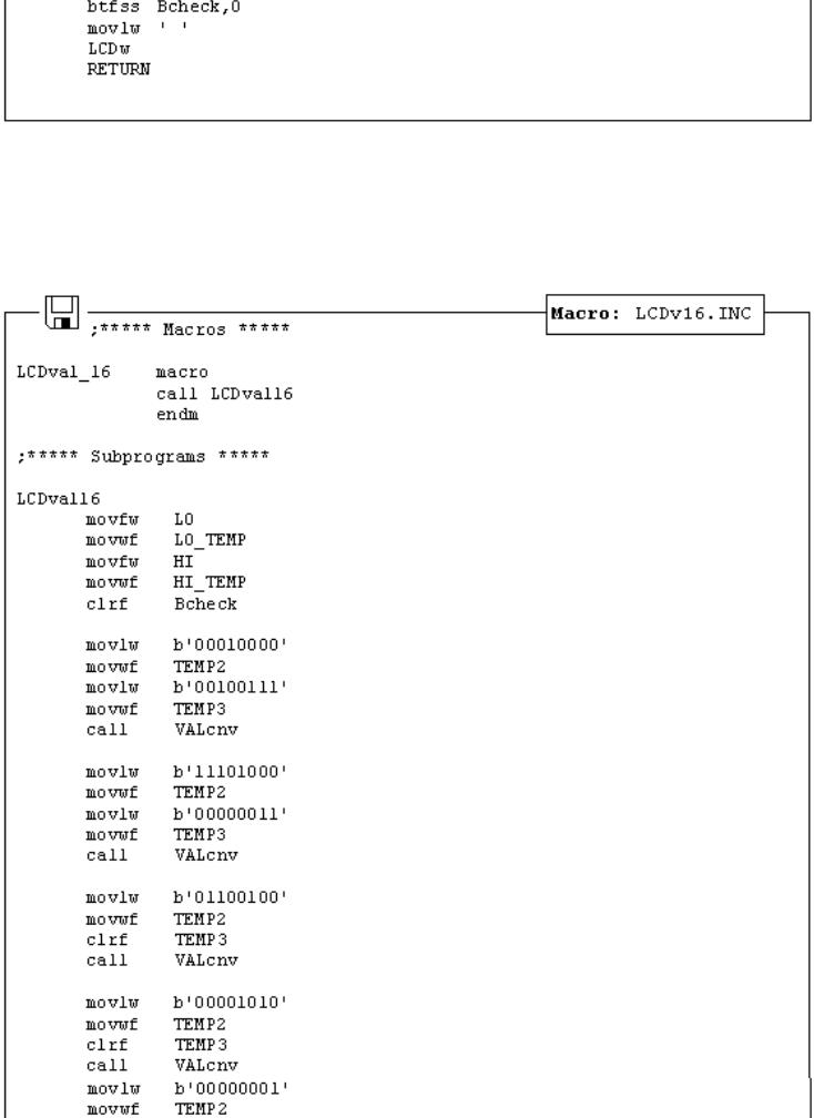
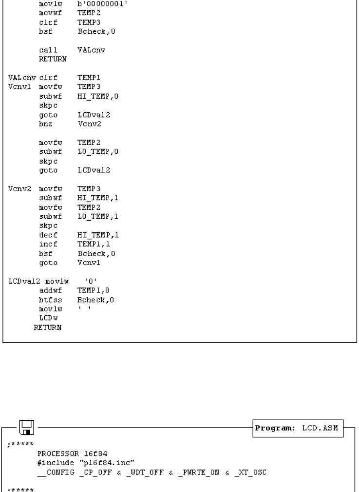
Macro LCDval_16 converts 16-bit binary number into decimal number from 0 to 65535 and displays it on LCD display. The following variables need to be declared in the main program: TEMP1, TEMP2, TEMP3, LO, HI, LO_TEMP, HI_TEMP, Bcheck. A 16-bit binary number is found in variables LO and HI. When a macro is executed, a decimal equivalent of this number will be displayed on LCD display. The leading zeros before the number will not be displayed.
http://www.mikroelektronika.co.yu/english/books/6_10Poglavlje.htm (10 of 13) [30/12/2001 16:54:44]
Chapter 6 - Samples
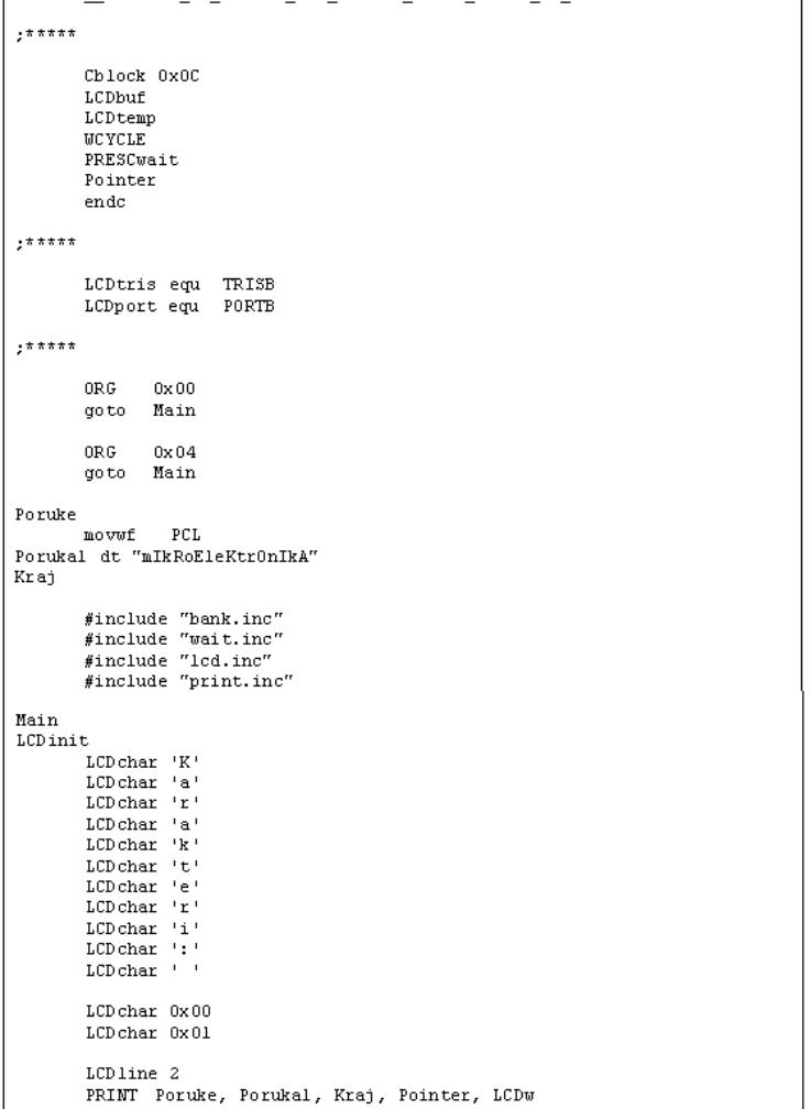
The main program is a demonstration of how to use the LCD display and generate new characters. At the beginning of a program, we need to declare variables LCDbuf and LCDtemp used by subprograms for the LCD as well as the microcontroller port connected to the LCD.
The program writes the message 'characters:' on the first row and shows two special characters '~' and '}'. In the second row, 'mikroElektronika' is displayed.
http://www.mikroelektronika.co.yu/english/books/6_10Poglavlje.htm (11 of 13) [30/12/2001 16:54:44]
Chapter 6 - Samples
http://www.mikroelektronika.co.yu/english/books/6_10Poglavlje.htm (12 of 13) [30/12/2001 16:54:44]

Chapter 6 - Samples
© Copyright 1999. mikroElektronika. All Rights Reserved. For any comments contact webmaster.
http://www.mikroelektronika.co.yu/english/books/6_10Poglavlje.htm (13 of 13) [30/12/2001 16:54:44]