

Chapter 6 - Samples
The Relay
The relay is an electromechanical device, which transforms an electrical signal into mechanical movement. It consists of a coil of insulated wire on a metal core, and a metal armature with one or more contacts.
When a supply voltage is delivered to the coil, current will flow and a magnetic field is produced that moves the armature to close one set of contacts and open another set. When power is removed from the relay, the magnetic flux in the coil collapses and produces a fairly high voltage in the opposite direction. This voltage can damage the driver transistor and thus a reverse-biased diode is connected across the coil to "short-out" the spike when it occurs.
http://www.mikroelektronika.co.yu/english/books/6_06Poglavlje.htm (1 of 4) [30/12/2001 16:54:26]
Chapter 6 - Samples
Connecting a relay to the microcontroller via a transistor
Many microcontrollers cannot drive a relay directly and so a driver transistor is required. A HIGH on the base of the transistor turns the transistor ON and this activates the relay. The relay can be connected to any electrical device via the contacts.
The 10k resistor on the base of the transistor limits the current from the microcontroller to that required by the transistor. The 10k between base and the negative rail prevents noise on the base from activating the relay. Thus only a clear signal from the microcontroller will activate the relay.
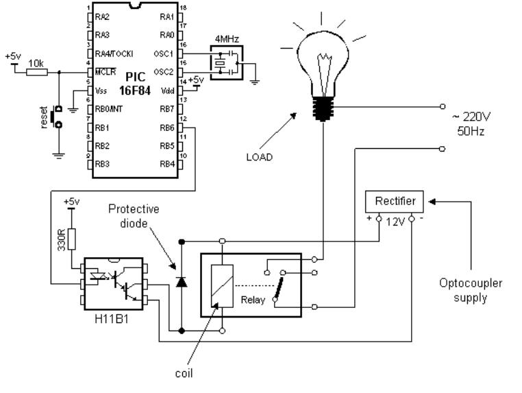
Connecting the optocoupler and relay to a microcontroller
A relay can also be activated via an optocoupler which at the same time strengthens the current from the output of the microcontroller and provides a high degree of isolation. High current optocouplers usually contain a 'darlington' output transistor to provide high output current.
Connecting via an optocoupler is recommended especially for microcontroller applications, where motors are activated as the commutator noise from the motor can get back to the microcontroller
http://www.mikroelektronika.co.yu/english/books/6_06Poglavlje.htm (2 of 4) [30/12/2001 16:54:26]
Chapter 6 - Samples
via the supply lines. The optocoupler drives a relay and the relay activates the motor.
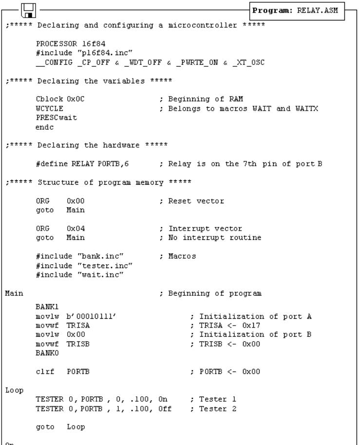
The figure below shows the program needed to activate the relay, and includes some of the already discussed macros.
http://www.mikroelektronika.co.yu/english/books/6_06Poglavlje.htm (3 of 4) [30/12/2001 16:54:26]

Chapter 6 - Samples
© Copyright 1999. mikroElektronika. All Rights Reserved. For any comments contact webmaster.
http://www.mikroelektronika.co.yu/english/books/6_06Poglavlje.htm (4 of 4) [30/12/2001 16:54:26]