


Chapter 6 - Samples
Optocouplers
Optocouplers combine a LED and photo-transistor in the same housing. The purpose of an optocoupler is to separate two parts of a circuit.
This is done for a number of reasons:
●Interference. One part of a circuit may be in a location where it picks up a lot of interference (such as from electric motors, welding equipment, petrol motors etc.) If the output of this circuit goes through an optocoupler to another circuit, only the intended signals will pass through the optocoupler. The interference signals will not have enough "strength" to activate the LED in the optocoupler and thus they are eliminated. To protect a section of the device. Typical examples are industrial units with lots of interferences which affect signals in the wires. If these interferences affect the function of control section, errors will occur and the unit will stop working.
●Simultaneous separation and intensification of a signal. A signal as low as 3v is able to activate an optocoupler and the output of the optocoupler can be connected to an input line of a microcontroller. The microcontroller requires an input swing of 5v and in this case the 3v signal is amplified to 5v. It can also be used to amplify the current of a signal. See below for use on the output line of a microcontroller for current amplification.
●High Voltage Separation. Optocouplers have inherent high voltage separation qualities. Since the LED is completely separate from the photo-transistor, optocouplers can exhibit voltage isolation of 3kv or higher.
Optocouplers can be used as input or output device. They can have additional functions such as Schmitt triggering (the output of a Schmitt trigger is either 0 or 1 - it changes slow rising and falling waveforms into definite low or high values). Optocouplers are packaged as a single unit or in groups of two or more in one housing. They are also called PHOTO INTERRUPTERS where a spoked wheel is inserted in a slot between the LED and phototransistor and each time the light is interrupted, the transistor produces a pulse.
Each optocoupler needs two supplies in order to function. They can be used with one supply, but the voltage isolation feature is lost.
Optocoupler on an input line
The way it works is simple: when a signal arrives, the LED within the optocoupler is turned on, and it shines on the base of a photo-transistor within the same housing. When the transistor is activated, the voltage between collector and emitter falls to 0.5V or less and the microcontroller sees this as a logic zero on its RA4 pin.
The example below is a counter, used for counting products on production line, determining motor
http://www.mikroelektronika.co.yu/english/books/6_05Poglavlje.htm (1 of 4) [30/12/2001 16:54:24]

Chapter 6 - Samples
speed, counting the number of revolutions of an axle etc.
Let the sensor be a micro-switch. Each time the switch is closed, the LED is illuminated. The LED 'transfers' the signal to the phototransistor and the operation of the photo-transistor delivers a LOW to input RA4 of a microcontroller. A program in the microcontroller will be needed to prevent false counting and an indicator connected to any of the outputs of the microcontroller will shows the current state of the counter.
Input line optocoupler example
http://www.mikroelektronika.co.yu/english/books/6_05Poglavlje.htm (2 of 4) [30/12/2001 16:54:24]
Chapter 6 - Samples
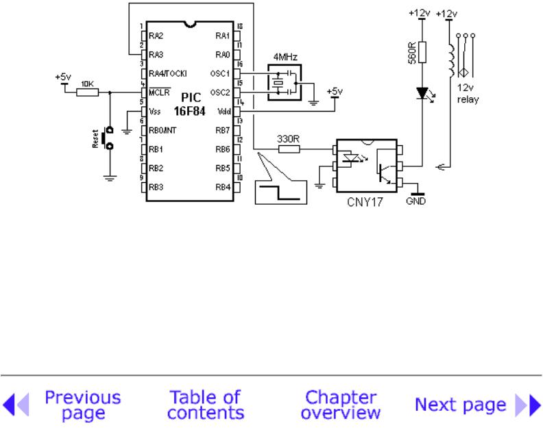
Optocoupler on an output line
An Optocoupler can be used to separate the output signal of a microcontroller from an output device. This may be needed for high voltage separation or current amplification. The output of some microcontrollers is limited to 25mA. The optocoupler will take the low-current signal from the microcontroller and drive a LED or relay, as shown below:
http://www.mikroelektronika.co.yu/english/books/6_05Poglavlje.htm (3 of 4) [30/12/2001 16:54:24]
Chapter 6 - Samples
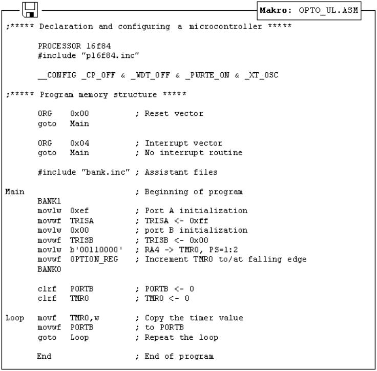
Output line optocoupler example
The program for this example is simple. By delivering a logic '1' to the fourth pin of port A, the LED will be turned on and the transistor will be activated in the optocoupler. Any device connected to the output of the optocoupler will be activated. The transistor current-limit is about 250mA.
© Copyright 1999. mikroElektronika. All Rights Reserved. For any comments contact webmaster.
http://www.mikroelektronika.co.yu/english/books/6_05Poglavlje.htm (4 of 4) [30/12/2001 16:54:24]