

Biomechanics Principles and Applications - Donald R. Peterson & Joseph D. Bronzino
.pdf3-32 |
Biomechanics |
Yp (mm)
12
8
4
0
–4
–8
–12 |
|
|
|
|
|
|
–12 |
–8 |
–4 |
0 |
4 |
8 |
12 |
Xp (mm)
FIGURE 3.32 Intersections of the instantaneous helical angles with the metacarpal sagittal plane. They are relative to one subject tested twice in different days. The origin of the graph is coincident with the calibrated center of the metacarpal head. The arrow indicates the direction of flexion. (From Fioretti S. 1994. In F. Schuind et al. (Eds.). Advances in the Biomechanics of the Hand and Wrist, pp. 363–375, New York, Plenum Press. With permission.)
TABLE 3.22 Location of Center of Rotation of
Trapeziometacarpal Joint
|
Mean ± SD (mm) |
|
Circumduction |
0.1 ± 1.3 |
|
X |
||
Y |
−0.6 ± 1.3 |
|
Z |
−0.5 ± 1.4 |
|
Flexion/extension (in x–y plane) |
|
|
X |
−4.2 ± 1.0 |
|
Centroid |
||
Radius |
2.0 ± 0.5 |
|
Y |
−0.4 ± 0.9 |
|
Centroid |
||
Radius |
1.6 ± 0.5 |
|
Abduction/adduction (in x–z plane) |
|
|
X |
|
± 1.7 |
Centroid |
6.7 |
|
Radius |
4.6 |
± 3.1 |
Z |
−0.2 |
± 0.7 |
Centroid |
||
Radius |
1.7 |
± 0.5 |
Note: The coordinate system is defined with the x-axis corresponding to internal/external rotation, the y-axis corresponding to abduction/adduction, and the z-axis corresponding to flexion/extension. The x-axis is positive in the distal direction, the y-axis is positive in the dorsal direction for the left hand and in the palmar direction for the right hand, and the z-axis is positive in the radial direction. The origin of the coordinate system was at the intersection of a line connecting the radial and ulnar prominences and a line connecting the volar and dorsal tubercles.
Source: Imaeda T., Niebur G., Cooney W.P., Linscheid R.L., and An K.N. 1994. J. Orthop. Res. 12: 197.

Joint-Articulating Surface Motion |
3-33 |
TABLE 3.23 Measurement of Axis Location and Values for
Axis Position in the Bonea
Interphalangeal joint flexion-extension axis (Figure 3.33a)
t/ T |
44 |
± 17% |
l /L |
90 |
± 5% |
|
5 |
± 2◦ |
β |
83 |
± 4◦ |
Metacarpophalangeal joint flexion-extension axis (Figure 3.33b)
t/ T |
57 |
± 17% |
l /L |
87 |
± 5% |
α |
101 |
± 6◦ |
β |
5 |
± 2◦ |
Metacarpophalangeal joint abduction-adduction axis (Figure 3.33c)
t/ T |
45 |
± 8% |
l /L |
83 |
± 13% |
α |
80 ± 9◦ |
|
β |
74 ± 8◦ |
|
M
a The angle of the abduction-adduction axis with respect to the flexion-extension axis is 84.8 ± 12.2◦ . The location and angulation of the K -wires of the axes with respect to the bones were measured ( , α, β) directly with a goniometer. The positions of the pins in the bones were measured (T, L ) with a Vernier caliper.
Source: Hollister A., Giurintano D.J., Buford W.L. et al. 1995. Clin. Orthop. Relat. Res. 320: 188.
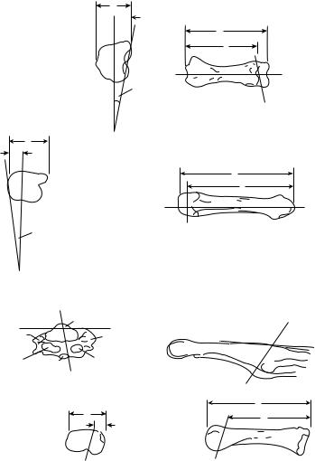
The axes of rotation of the thumb interphalangeal and metacarpophalangeal joint were located using a mechanical device [Hollister et al., 1995]. The physiologic motion of the thumb joints occur about these axes (Figure 3.33 and Table 3.23). The interphalangeal joint axis is parallel to the flexion crease of the joint and is not perpendicular to the phalanx. The metacarpophalangeal joint has two fixed axes: a fixed flexion–extension axis just distal and volar to the epicondyles, and an abduction–adduction axis related to the proximal phalanx passing between the sesamoids. Neither axis is perpendicular to the phalanges.
3.8 Summary
It is important to understand the biomechanics of joint-articulating surface motion. The specific characteristics of the joint will determine the musculoskeletal function of that joint. The unique geometry of the joint surfaces and the surrounding capsule ligamentous constraints will guide the unique characteristics of the articulating surface motion. The range of joint motion, the stability of the joint, and the ultimate functional strength of the joint will depend on these specific characteristics. A congruent joint usually has a relatively limited range of motion but a high degree of stability, whereas a less congruent joint will have a relatively larger range of motion but less degree of stability. The characteristics of the joint-articulating surface will determine the pattern of joint contact and the axes of rotation. These characteristics will regulate the stresses on the joint surface that will influence the degree of degeneration of articular cartilage in an anatomic joint and the amount of wear of an artificial joint.
Acknowledgment
The authors thank Barbara Iverson-Literski for her careful preparation of the manuscript.
3-34 |
Biomechanics |
(a) |
|
 t
t
L
Radial |
l |
Radial
|
|
|
|
|
|
|
|
|
Flexion–extension |
|
|
|
|
axis |
(b) |
|
Flexion–extension |
|
|
|
t |
|
axis |
|
|
|
Radial |
|
L |
|
|
|
|
I |
|
|
Ulnar |
|
Radial |
|
|
|
||
|
|
|
|
Ulnar |
|
|
|
Flexion–extension |
|
|
|
axis |
|
|
|
|
|
|
|
Flexion–extension |
|
|
|
|
axis |
|
|
(c) |
|
|
Abduction–adduction |
|
|
axis |
|
Colateral |
EPB |
|
|
Colateral ligament |
|
||
ligament |
|
|
|
|
|
|
|
Sesamoid |
Sesamoid |
|
|
(radial) |
FPL |
(Ulnar) |
|
|
Abduction–adduction |
|
|
|
axis |
|
|
|
|
|
L |
|
|
|
I |
|
|
t |
|
|
|
|
|
|
Ulnar |
Radial |
|
|
Abduction–adduction |
Abduction–adduction |
|
|
axis |
|
axis |
FIGURE 3.33 (a) The angles and length and breadth measurements defining the axis of rotation of the interphalangeal joint of the right thumb. (t/ T = ratio of anatomic plane diameter; l /L = ratio of length). (b) The angles and length and breadth measurements of the metacarpophalangeal flexion–extension axis’ position in the metacarpal.
(c) The angles and length and breadth measurements that locate the metacarpophalangeal abduction–adduction axis. The measurements are made in the metacarpal when the metacapophalangeal joint is at neutral flexion extension. The measurements are made relative to the metacarpal because the axis passes through this bone, not the proximal phalanx with which it moves. This method of recording the abduction–adduction measurements allows the measurements of the axes to each other at a neutral position to be made. The metacarpophalangeal abduction–adduction axis passes through the volar plate of the proximal phalanx. (From Hollister A., Giurintano D.J., Buford W.L. et al. Clin. Orthop. Relat. Res. 320: 188, 1995.)
Joint-Articulating Surface Motion |
3-35 |
References
Ahmed A.M., Burke D.L., and Hyder A. 1987. Force analysis of the patellar mechanism. J. Orthop. Res. 5: 1, 69.
Allard P., Duhaime M., Labelle H. et al. 1987. Spatial reconstruction technique and kinematic modeling of the ankle. IEEE Eng. Med. Biol. 6: 31.
An K.N. and Cooney W.P. 1991. Biomechanics, Section II. The hand and wrist. In B.F. Morrey (Ed.), Joint Replacement Arthroplasty, pp. 137–146, New York, Churchill Livingstone.
Anderson D.D., Bell A.L., Gaffney M.B. et al. 1996. Contact stress distributions in malreduced intraarticular distal radius fractures. J. Orthop. Trauma 10: 331.
Andriacchi T.P., Stanwyck T.S., and Galante J.O. 1986. Knee biomechanics in total knee replacement.
J. Arthroplasty 1: 211.
Ateshian G.A., Ark J.W., Rosenwasser M.D., et al. 1995. Contact areas in the thumb carpometacarpal joint.
J. Orthop. Res. 13: 450.
Athesian J.A., Rosenwasser M.P., and Mow V.C. 1992. Curvature characteristics and congruence of the thumb carpometacarpal joint: differences between female and male joints. J. Biomech. 25: 591.
Barnett C.H. and Napier J.R. 1952. The axis of rotation at the ankle joint in man. Its influence upon the form of the talus and the mobility of the fibula. J. Anat. 86: 1.
Basmajian J.V. and Bazant F.J. 1959. Factors preventing downward dislocation of the adducted shoulder joint. An electromyographic and morphological study. J. Bone Joint Surg. 41A: 1182.
Boileau P. and Walch G. 1997. The three-dimensional geometry of the proximal humerus. J. Bone Joint Surg. 79B: 857.
D’Ambrosia R.D., Shoji H., and Van Meter J. 1976. Rotational axis of the ankle joint: comparison of normal and pathological states. Surg. Forum 27: 507.
Davy D.T., Kotzar D.M., Brown R.H. et al. 1989. Telemetric force measurements across the hip after total arthroplasty. J. Bone Joint Surg. 70A: 45.
Doody S.G., Freedman L., and Waterland J.C. 1970. Shoulder movements during abduction in the scapular plane. Arch. Phys. Med. Rehabil. 51: 595.
Draganich L.F., Andriacchi T.P., and Andersson G.B.J. 1987. Interaction between intrinsic knee mechanics and the knee extensor mechanism. J. Orthop. Res. 5: 539.
Driscoll H.L., Christensen J.C., and Tencer A.F. 1994. Contact characteristics of the ankle joint. J. Am. Pediatr. Med. Assoc. 84: 491.
Elftman H. 1945. The orientation of the joints of the lower extremity. Bull. Hosp. Joint Dis. 6: 139. Engsberg J.R. 1987. A biomechanical analysis of the talocalcaneal joint in vitro. J. Biomech. 20: 429. Farahmand F., Senavongse W., and Amis A.A. 1998. Quantitative study of the quadriceps muscles and
trochlear groove geometry related to instability of the patellofemoral joint. J. Orthop. Res. 16: 136. Fioretti S. 1994. Three-dimensional in-vivo kinematic analysis of finger movement. In F. Schuind
et al. (Eds.), Advances in the Biomechanics of the Hand and Wrist, pp. 363–375, New York, Plenum. Freedman L. and Munro R.R. 1966. Abduction of the arm in the scapular plane: scapular and glenohumeral
movements. A roentgenographic study. J. Bone Joint Surg. 48A: 1503.
Goel V.K., Singh D., and Bijlani V. 1982. Contact areas in human elbow joints. J. Biomech. Eng. 104: 169–175.
Goodfellow J., Hungerford D.S., and Zindel M. 1976. Patellofemoral joint mechanics and pathology. J. Bone Joint Surg. 58B: 287.
Hamrick M.W. 1996. Articular size and curvature as detriments of carpal joint mobility and stability in strepsirhine primates. J. Morphol. 230: 113.
Hartford J.M., Gorczyca J.T., McNamara J.L. et al. 1985. Tibiotalar contact area. Clin. Orthop. 320: 82. Hicks J.H. 1953. The mechanics of the foot. The joints. J. Anat. 87: 345–357.
Hollister A., Buford W.L., Myers L.M. et al. 1992. The axes of rotation of the thumb carpometacarpal joint.
J. Orthop. Res. 10: 454.
Hollister A., Guirintano D.J., Bulford W.L. et al. 1995. The axes of rotation of the thumb interphalangeal and metacarpophalangeal joints. Clin. Orthop. 320: 188.
3-36 |
Biomechanics |
Horii E., Garcia-Elias M., An K.N. et al. 1990. Effect of force transmission across the carpus in procedures used to treat Kienbock’s¨ disease. J. Bone Joint Surg. 15A: 393.
Huberti H.H. and Hayes W.C. 1984. Patellofemoral contact pressures: the influence of Q-angle and tendofemoral contact. J. Bone Joint Surg. 66A: 715.
Iannotti J.P., Gabriel J.P., Schneck S.L. et al. 1992. The normal glenohumeral relationships: an anatomical study of 140 shoulders. J. Bone Joint Surg. 74A: 491.
Imaeda T., Niebur G., Cooney W.P. et al. 1994. Kinematics of the normal trapeziometacarpal joint. J. Orthop. Res. 12: 197.
Inman V.T., Saunders J.B., and Abbott L.C. 1944. Observations on the function of the shoulder joint.
J. Bone Joint Surg. 26A: 1.
Inman V.T. 1976. The Joints of the Ankle, Baltimore, Williams and Wilkins.
Inman V.T. and Mann R.A. 1979. Biomechanics of the foot and ankle. In V.T. Inman (Ed.), DuVrie’s Surgery of the Foot, St Louis, Mosby.
Iseki F. and Tomatsu T. 1976. The biomechanics of the knee joint with special reference to the contact area.
Keio. J. Med. 25: 37.
Isman R.E. and Inman V.T. 1969. Anthropometric studies of the human foot and ankle. Pros. Res. 10–11: 97.
Jobe C.M. and Iannotti J.P. 1995. Limits imposed on glenohumeral motion by joint geometry. J. Shoulder Elbow Surg. 4: 281.
Kapandji I.A. 1987. The Physiology of the Joints, Vol. 2, Lower Limb, Edinburgh, Churchill-Livingstone, Edinburgh.
Karduna A.R., Williams G.R., Williams J.I. et al. 1996. Kinematics of the glenohumeral joint: influences of muscle forces, ligamentous constraints, and articular geometry. J. Orthop. Res. 14: 986.
Kent B.E. 1971. Functional anatomy of the shoulder complex. A review. Phys. Ther. 51: 867.
Kimizuka M., Kurosawa H., and Fukubayashi T. 1980. Load-bearing pattern of the ankle joint. Contact area and pressure distribution. Arch. Orthop. Trauma Surg. 96: 45–49.
Kinzel G.L., Hall A.L., and Hillberry B.M. 1972. Measurement of the total motion between two body segments: Part I. Analytic development. J. Biomech. 5: 93.
Kirby K.A. 1947. Methods for determination of positional variations in the subtalar and transverse tarsal joints. Anat. Rec. 80: 397.
Kobayashi M., Berger R.A., Nagy L. et al. 1997. Normal kinematics of carpal bones: a three-dimensional analysis of carpal bone motion relative to the radius. J. Biomech. 30: 787.
Kurosawa H., Walker P.S., Abe S. et al. 1985. Geometry and motion of the knee for implant and orthotic design. J. Biomech. 18: 487.
Lewis J.L. and Lew W.D. 1978. A method for locating an optimal “fixed” axis of rotation for the human knee joint. J. Biomech. Eng. 100: 187.
Libotte M., Klein P., Colpaert H. et al. 1982. Contribution a` l’etude´ biomecanique´ de la pince malleolaire´.
Rev. Chir. Orthop. 68: 299.
Lippitts B., Vanderhooft J.E., Harris S.L. et al. 1993. Glenohumeral stability from concavity-compression: a quantitative analysis. J. Shoulder Elbow Surg. 2: 27.
Matsuda S., Miura H., Nagamine R., Mawatari T., Tokunaga M., Nabeyama R., and Iwamoto Y. 2004. Anatomical analysis of the femoral condyle in normal and osteoarthritic knees. J. Orthop. Res. 22: 104–109.
Macko V.W., Matthews L.S., Zwirkoski P. et al. 1991. The joint contract area of the ankle: the contribution of the posterior malleoli. J. Bone Joint Surg. 73A: 347.
Manter J.T. 1941. Movements of the subtalar and transverse tarsal joints. Anat. Rec. 80: 397–402.
Maquet P.G., Vandberg A.J., and Simonet J.C. 1975. Femorotibial weight bearing areas: experimental determination. J. Bone Joint Surg. 57A: 766–771.
McPherson E.J., Friedman R.J., An Y.H. et al. 1997. Anthropometric study of normal glenohumeral relationships. J. Shoulder Elbow Surg. 6: 105.
Joint-Articulating Surface Motion |
3-37 |
Merz B., Eckstein F., Hillebrand S. et al. 1997. Mechanical implication of humero-ulnar incongruity-finite element analysis and experiment. J. Biomech. 30: 713.
Miyanaga Y., Fukubayashi T., and Kurosawa H. 1984. Contact study of the hip joint: load deformation pattern, contact area, and contact pressure. Arch. Orth. Trauma Surg. 103: 13–17.
Morrey B.F. and An K.N. 1990. Biomechanics of the shoulder. In C.A. Rockwood and F.A. Matsen (Eds.), The Shoulder, pp. 208–245, Philadelphia, Saunders.
Morrey B.F. and Chao E.Y.S. 1976. Passive motion of the elbow joint: a biomechanical analysis. J. Bone Joint Surg. 58A: 501.
Nahass B.E., Madson M.M., and Walker P.S. 1991. Motion of the knee after condylar resurfacing — an in vivo study. J. Biomech. 24: 1107.
Paar O., Rieck B., and Bernett P. 1983. Experimentelle untersuchungen uber¨ belastungsabhangige¨ Drukund Kontaktflachenverl¨aufe¨ an den Fussgelenken. Unfallheilkunde 85: 531.
Pagowski S. and Piekarski K. 1977. Biomechanics of metacarpophalangeal joint. J. Biomech. 10: 205. Palmer A.K. and Werner F.W. 1984. Biomechanics of the distal radio–ulnar joint. Clin. Orthop. 187: 26. Parlasca R., Shoji H., and D’Ambrosia R.D. 1979. Effects of ligamentous injury on ankle and subtalar
joints. A kinematic study. Clin. Orthop. 140: 266.
Pellegrini V.S., Olcott V.W., and Hollenberg C. 1993. Contact patterns in the trapeziometacarpal joint: the role of the palmar beak ligament. J. Hand Surg. 18A: 238.
Pereira D.S., Koval K.J., Resnick R.B. et al. 1996. Tibiotalar contact area and pressure distribution: the effect of mortise widening and syndesmosis fixation. Foot Ankle 17: 269.
Poppen N.K. and Walker P.S. 1976. Normal and abnormal motion of the shoulder. J. Bone Joint Surg. 58A: 195.
Ramsey P.L. and Hamilton W. 1976. Changes in tibiotalar area of contact caused by lateral talar shift.
J. Bone Joint Surg. 58A: 356.
Rastegar J., Miller N., and Barmada R. 1980. An apparatus for measuring the load-displacement and load-dependent kinematic characteristics of articulating joints — application to the human ankle.
J. Biomech. Eng. 102: 208.
Rosenbaum D., Eils E., and Hillmann A. 2003. Changes in talocrural joint contact stress characteristics after simulated rotationplasty. J. Biomech. 36: 81–86.
Root M.L., Weed J.H., Sgarlato T.E., and Bluth D.R. 1966. Axis of motion of the subtalar joint. J. Am. Pediatry Assoc. 56: 149.
Saha A.K. 1971. Dynamic stability of the glenohumeral joint. Acta Orthop. Scand. 42: 491.
Sammarco G.J., Burstein A.J., and Frankel V.H. 1973. Biomechanics of the ankle: a kinematic study. Orthop. Clin. North Am. 4: 75–96.
Sato S. 1995. Load transmission through the wrist joint: a biomechanical study comparing the normal and pathological wrist. Nippon Seikeigeka Gakkai Zasshi-Journal of the Japanese Orthopaedic Association 69: 470–483.
Scarvell J.M., Smith P.N., Refshauge K.M., Galloway H.R., and Woods K.R. 2004. Evaluation of a method to map tibiofemoral contact points in the normal knee using MRI. J. Orthop. Res. 22: 788–793.
Schuind F.A., Linscheid R.L., An K.N. et al. 1992. Changes in wrist and forearm configuration with grasp and isometric contraction of elbow flexors. J. Hand Surg. 17A: 698.
Shephard E. 1951. Tarsal movements. J. Bone Joint Surg. 33B: 258.
Shiba R., Sorbie C., Siu D.W. et al. 1988. Geometry of the humeral–ulnar joint. J. Orthop. Res. 6: 897. Singh A.K., Starkweather K.D., Hollister A.M. et al. 1992. Kinematics of the ankle: a hinge axis model. Foot
Ankle 13: 439.
Soslowsky L.J., Flatow E.L., Bigliani L.U. et al. 1992. Quantitation of in situ contact areas at the glenohumeral joint: a biomechanical study. J. Orthop. Res. 10: 524.
Spoor C.W. and Veldpaus F.E. 1980. Rigid body motion calculated from spatial coordinates of markers.
J. Biomech. 13: 391.
Stormont T.J., An K.A., Morrey B.F. et al. 1985. Elbow joint contact study: comparison of techniques.
J. Biomech. 18: 329.
3-38 |
Biomechanics |
Tamai K., Ryu J., An K.N. et al. 1988. Three-dimensional geometric analysis of the metacarpophalangeal joint. J. Hand Surg. 13A: 521.
Tanaka S., An K.N., and Morrey B.F. 1998. Kinematics and laxity of ulnohumeral joint under valgus–varus stress. J. Musculoskeletal Res. 2: 45.
Tonnis¨ D. 1987. Congenital Dysplasia and Dislocation of the Hip and Shoulder in Adults, pp. 1–12, Berlin, Springer-Verlag.
Van Eijden T.M.G.J., Kouwenhoven E., Verburg J. et al. 1986. A mathematical model of the patellofemoral joint. J. Biomech. 19: 219.
Van Langelaan E.J. 1983. A kinematical analysis of the tarsal joints. An x-ray photogrammetric study. Acta Orthop. Scand. 204: 211.
Viegas S.F., Tencer A.F., Cantrell J. et al. 1987. Load transfer characteristics of the wrist: Part I. The normal joint. J. Hand Surg. 12A: 971.
Viegas S.F., Patterson R.M., Peterson P.D. et al. 1989. The effects of various load paths and different loads on the load transfer characteristics of the wrist. J. Hand Surg. 14A: 458.
Viegas S.F., Patterson R.M., Todd P. et al. October 7, 1990. Load transfer characteristics of the midcarpal joint. Presented at Wrist Biomechanics Symposium, Wrist Biomechanics Workshop, Mayo Clinic, Rochester, MN.
Von Lanz D. and Wauchsmuth W. 1938. Das H¨uftgelenk, Praktische Anatomie I Bd, pp. 138–175, Teil 4: Bein und Statik, Berlin, Springer-Verlag.
Wagner U.A., Sangeorzan B.J., Harrington R.M. et al. 1992. Contact characteristics of the subtalar joint: load distribution between the anterior and posterior facets. J. Orthop. Res. 10: 535.
Walker P.S. and Erhman M.J. 1975. Laboratory evaluation of a metaplastic type of metacarpophalangeal joint prosthesis. Clin. Orthop. 112: 349.
Wang C.-L., Cheng C.-K., Chen C.-W. et al. 1994. Contact areas and pressure distributions in the subtalar joint. J. Biomech. 28: 269.
Woltring H.J., Huiskes R., deLange A., and Veldpaus F.E. 1985. Finite centroid and helical axis estimation from noisy landmark measurements in the study of human joint kinematics. J. Biomech. 18: 379.
Yoshioka Y., Siu D., and Cooke T.D.V. 1987. The anatomy and functional axes of the femur. J. Bone Joint Surg. 69A: 873.
Yoshioka Y., Siu D., Scudamore R.A. et al. 1989. Tibial anatomy in functional axes. J. Orthop. Res. 7: 132. Youm Y., McMurty R.Y., Flatt A.E. et al. 1978. Kinematics of the wrist: an experimental study of radioulnar
deviation and flexion/extension. J. Bone Joint Surg. 60A: 423.
Zuckerman J.D. and Matsen F.A. 1989. Biomechanics of the elbow. In M. Nordine and V.H. Frankel (Eds.),
Basic Biomechanics of the Musculoskeletal System, pp. 249–260, Philadelphia, Lea & Febiger.

4
Joint Lubrication
|
4.1 |
Introduction . . . . . . . . . . . . . . . . . . . . . . . . . . . . . . . . . . . . . . . . . . |
4-2 |
|
|
4.2 |
Tribology . . . . . . . . . . . . . . . . . . . . . . . . . . . . . . . . . . . . . . . . . . . . . |
4-2 |
|
|
|
Friction • |
Wear and Surface Damage |
|
|
4.3 |
Lubrication . . . . . . . . . . . . . . . . . . . . . . . . . . . . . . . . . . . . . . . . . . . |
4-3 |
|
|
|
Hydrodynamic Lubrication Theories • Transition from |
|
|
|
|
Hydrodynamic to Boundary Lubrication |
|
|
|
4.4 |
Synovial Joints . . . . . . . . . . . . . . . . . . . . . . . . . . . . . . . . . . . . . . . . |
4-7 |
|
|
4.5 |
Theories on the Lubrication of Natural and Normal |
4-8 |
|
|
|
Synovial Joints . . . . . . . . . . . . . . . . . . . . . . . . . . . . . . . . . . . . . . . . |
||
|
4.6 |
In Vitro Cartilage Wear Studies . . . . . . . . . . . . . . . . . . . . . . . . |
4-11 |
|
|
4.7 |
Biotribology and Arthritis: Are There Connections? . . . . |
4-15 |
|
|
4.8 |
Recapitulation and Final Comments . . . . . . . . . . . . . . . . . . . |
4-17 |
|
|
|
Terms and Definitions • Experimental Contact Systems |
|
|
|
|
• Fluids and Materials Used as Lubricants in In Vitro |
|
|
|
|
Biotribology Studies • The Preoccupation with Rheology and |
|
|
|
|
Friction • |
The Probable Existence of Various Lubrication |
|
|
|
Regimes • |
Recent Developments |
|
|
4.9 |
Conclusions . . . . . . . . . . . . . . . . . . . . . . . . . . . . . . . . . . . . . . . . . . |
4-21 |
|
Michael J. Furey |
Acknowledgments . . . . . . . . . . . . . . . . . . . . . . . . . . . . . . . . . . . . . . . . . . |
4-22 |
||
Virginia Polytechnic Institute |
References . . . . |
. . . . . . . . . . . . . . . . . . . . . . . . . . . . . . . . . . . . . . . . . . . . . . |
4-22 |
|
and State University |
Further Information . . . . . . . . . . . . . . . . . . . . . . . . . . . . . . . . . . . . . . . . |
4-25 |
||
The Fabric of the Joints in the Human Body is a subject so much the more entertaining, as it must strike every one that considers it attentively with an Idea of fine Mechanical Composition. Wherever the Motion of one Bone upon another is requisite, there we find an excellent Apparatus for rendering that Motion safe and free: We see, for Instance, the Extremity of one Bone molded into an orbicular Cavity, to receive the Head of another, in order to afford it an extensive Play. Both are covered with a smooth elastic Crust, to prevent mutual Abrasion; connected with strong Ligaments, to prevent Dislocation; and inclosed in a Bag that contains a proper Fluid Deposited there, for lubricating the Two contiguous Surfaces. So much in general.
The above is the opening paragraph of the classic paper by the surgeon, Sir William Hunter, “Of the Structure and Diseases of Articulating Cartilages,” which he read to a meeting of the Royal Society, June 2, 1743 [1]. Since then, a great deal of research has been carried out on the subject of synovial joint lubrication. However, the mechanisms involved are still unknown.
4-1

4-2 |
Biomechanics |
4.1 Introduction
The purpose of this article is twofold: (1) to introduce the reader to the subject of tribology — the study of friction, wear, and lubrication; and (2) to extend this to the topic of biotribology, which includes the lubrication of natural synovial joints. It is not meant to be an exhaustive review of joint lubrication theories; space does not permit this. Instead, major concepts or principles will be discussed not only in the light of what is known about synovial joint lubrication but perhaps more importantly what is not known. Several references are given for those who wish to learn more about the topic. It is clear that synovial joints are by far the most complex and sophisticated tribological systems that exist. We shall see that although numerous theories have been put forth to attempt to explain joint lubrication, the mechanisms involved are still far from being understood. And when one begins to examine possible connections between tribology and degenerative joint disease or osteoarthritis, the picture is even more complex and controversial. Finally, this article does not treat the (1) tribological behavior of artificial joints or partial joint replacements,
(2) the possible use of elastic or poroplastic materials as artificial cartilage, and (3) new developments in cartilage repair using transplanted chondrocytes. These are separate topics, which would require detailed discussion and additional space.
4.2 Tribology
The word tribology, derived from the Greek “to rub,” covers all frictional processes between solid bodies moving relative to one another that are in contact [2]. Thus tribology may be defined as the study of friction, wear, and lubrication.
Tribological processes are involved whenever one solid slides or rolls against another, as in bearings, cams, gears, piston rings and cylinders, machining and metalworking, grinding, rock drilling, sliding electrical contacts, frictional welding, brakes, the striking of a match, music from a cello, articulation of human synovial joints (e.g., hip joints), machinery, and in numerous less obvious processes (e.g., walking, holding, stopping, writing, and the use of fasteners such as nails, screws, and bolts).
Tribology is a multidisciplinary subject involving at least the areas of materials science, solid and surface mechanics, surface science and chemistry, rheology, engineering, mathematics, and even biology and biochemistry. Although tribology is still an emerging science, interest in the phenomena of friction, wear, and lubrication is an ancient one. Unlike thermodynamics, there are no generally accepted laws in tribology. But there are some important basic principles needed to understand any study of lubrication and wear and even more so in a study of biotribology or biological lubrication phenomena. These basic principles follow.
4.2.1 Friction
Much of the early work in tribology was in the area of friction — possibly because frictional effects are more readily demonstrated and measured. Generally, early theories of friction dealt with dry or unlubricated systems. The problem was often treated strictly from a mechanical viewpoint, with little or no regard for the environment, surface films, or chemistry.
In the first place, friction may be defined as the tangential resistance that is offered to the sliding of one solid body over another. Friction is the result of many factors and cannot be treated as something as singular as density or even viscosity. Postulated sources of friction have included (1) the lifting of one asperity over another (increase in potential energy), (2) the interlocking of asperities followed by shear, (3) interlocking followed by plastic deformation or plowing, (4) adhesion followed by shear,
(5) elastic hysteresis and waves of deformation, (6) adhesion or interlocking followed by tensile failure, (7) intermolecular attraction, (8) electrostatic effects, and (9) viscous drag. The coefficient of friction, indicated in the literature by μ or f , is defined as the ratio F / W where F = friction force and W = the normal load. It is emphasized that friction is a force and not a property of a solid material or lubricant.

Joint Lubrication |
4-3 |
4.2.2 Wear and Surface Damage
One definition of wear in a tribological sense is that it is the progressive loss of substance from the operating surface of a body as a result of relative motion at the surface. In comparison with friction, very little theoretical work has been done on the extremely important area of wear and surface damage. This is not too surprising in view of the complexity of wear and how little is known of the mechanisms by which it can occur. Variations in wear can be, and often are, enormous compared with variations in friction. For example, practically all the coefficients of sliding friction for diverse dry or lubricated systems fall within a relatively narrow range of 0.1 to 1. In some cases (e.g., certain regimes of hydrodynamic or “boundary” lubrication), the coefficient of friction may be <0.1 and as low as 0.001. In other cases (e.g., very clean unlubricated metals in vacuum), friction coefficients may exceed one. Reduction of friction by a factor of two through changes in design, materials, or lubricant would be a reasonable, although not always attainable, goal. On the other hand, it is not uncommon for wear rates to vary by a factor of 100, 1000, or even more.
For systems consisting of common materials (e.g., metals, polymers, ceramics), there are at least four main mechanisms by which wear and surface damage can occur between solids in relative motion: (1) abrasive wear, (2) adhesive wear, (3) fatigue wear, and (4) chemical or corrosive wear. A fifth, fretting wear and fretting corrosion, combines elements of more than one mechanism. For complex biological materials such as articular cartilage, most likely other mechanisms are involved.
Again, wear is the removal of material. The idea that friction causes wear and therefore, low friction means low wear, is a common mistake. Brief descriptions of five types of wear; abrasive, adhesive, fatigue, chemical or corrosive, and fretting — may be found in Reference 2 as well as in other references in this article. Next, it may be useful to consider some of the major concepts of lubrication.
4.3 Lubrication
Lubrication is a process of reducing friction and/or wear (or other forms of surface damage) between relatively moving surfaces by the application of a solid, liquid, or gaseous substance (i.e., a lubricant). Since friction and wear do not necessarily correlate with each other, the use of the word and in place of and/or in the above definition is a common mistake to be avoided. The primary function of a lubricant is to reduce friction or wear or both between moving surfaces in contact with each other.
Examples of lubricants are wide and varied. They include automotive engine oils, wheel bearing greases, transmission fluids, electrical contact lubricants, rolling oils, cutting fluids, preservative oils, gear oils, jet fuels, instrument oils, turbine oils, textile lubricants, machine oils, jet engine lubricants, air, water, molten glass, liquid metals, oxide films, talcum powder, graphite, molybdenum disulfide, waxes, soaps, polymers, and the synovial fluid in human joints.
A few general principles of lubrication may be mentioned here:
1.The lubricant must be present at the place where it can function.
2.Almost any substance under carefully selected or special conditions can be shown to reduce friction or wear in a particular test, but that does not mean these substances are lubricants.
3.Friction and wear do not necessarily go together. This is an extremely important principle that applies to nonlubricated (dry) as well as lubricated systems. It is particularly true under conditions of “boundary lubrication,” to be discussed later. An additive may reduce friction and increase wear, reduce wear and increase friction, reduce both or increase both. Although the reasons are not fully understood, this is an experimental observation. Thus, friction and wear should be thought of as separate phenomena — an important point when we discuss theories of synovial joint lubrication.
4.The effective or active lubricating film in a particular system may or may not consist of the original or bulk lubricant phase.
In a broad sense, it may be considered that the main function of a lubricant is to keep the surfaces apart so that interaction (e.g., adhesion, plowing, and shear) between the solids cannot occur; thus friction and wear can be reduced or controlled.