

Biomechanics Principles and Applications - Donald R. Peterson & Joseph D. Bronzino
.pdf5-8 |
Biomechanics |
This process may then be repeated for the shank and thigh by using distal joint loads to solve for the proximal intersegmental reactions. The mechanical power associated with an intersegmental moment and the corresponding joint angular velocity may be computed from the vector dot product of the two vectors, for example, ankle power is computed through MA · A where A is the angular velocity of the foot relative
˜
to the shank. Readers are referred to descriptions by Ounpuu et al. [33] and Palladino and Davis [34] for more details associated with this process.
Although sometimes referred to as “muscle moments,” these net intersegmental moments reflect the moments produced by several mechanisms, for example, ligamentous forces, passive muscle and tendon force, and active muscle contractile force, in response to external loads. Currently, the evaluation of individual muscle forces in a patient population is not feasible because optimization strategies that may be successful for normal ambulation, for example, Chao and Rim [35], Anderson and Pandy [36], may not be appropriate for pathological muscle behavior, for example, spasticity, overactivity, hyperor hypotonicity.
With respect to assumptions associated with these gait models, the body segments are assumed to be rigid, for example, soft tissue movement relative to underlying bony structures is small. The external markers are assumed to move with the underlying anatomical references. In this way, estimated joint center locations are assumed to remain fixed relative to the respective segmental coordinate systems, for example, the knee center is fixed relative to the thigh coordinate system. Moreover, the mass distribution changes during motion are assumed to be negligible. Consequently, marker or instrumentation attachment sites must be carefully selected, for example, over tendonous structures of the distal shank as opposed to the more proximal muscle masses of the gastrocnemius and soleus.
5.4 Illustrative Clinical Example
As indicated earlier, the information available for clinical gait interpretation may include static physical examination measures, stride and temporal data, segment and joint kinematics, joint kinetics, electromyograms, and a video record. With this information, the clinical team can assess the patient’s gait deviations, attempt to identify the etiology of the abnormalities and recommend treatment alternatives. In this way, clinicians are able to isolate the biomechanical insufficiency that may produce a locomotive impairment and require a compensatory response from the patient. For example, a patient may excessively elevate a pelvis (compensatory) in order to gain additional foot clearance in swing, which is perhaps inadequate due to a weak ankle dorsiflexor (primary problem).
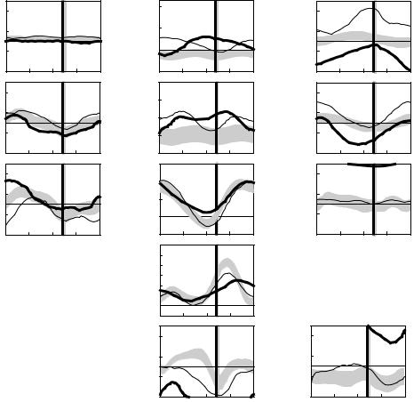
The following example illustrates how gait analysis data are used in the treatment decision-making process for a six-year-old child with cerebral palsy, left spastic hemiplegia. Initially, all gait and clinical examination data are reviewed and a list of primary problems and possible causes is generated. The reviewed data would include three-dimensional kinematic data (Figure 5.4), and kinetic data (Figure 5.5) and dynamic EMG data (Figure 5.6).
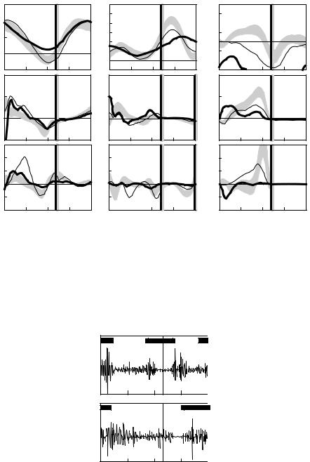
In the sagittal plane, increased left plantar flexion in stance and swing (Figure 5.4, Point A) is secondary to spasticity of the ankle plantar flexor muscles as the patient has normal passive range of motion of the ankle and can stand plantigrade. Premature plantar flexion of the right ankle in mid stance (Figure 5.4, Point B) is a vault compensation as the patient could isolate motion about the right ankle on clinical examination and produce an internal dorsiflexor moment during loading response (Figure 5.5, Point A). Increased left knee flexion at initial contact (Figure 5.4, Point C) is secondary to hamstring muscle spasticity/tightness (appreciated during the clinical examination) as well as overactivity of the hamstrings during gait (seen in the EMG data, Figure 5.6, Point A). Reduced left knee flexion in swing (Figure 5.4, Point D) is secondary to rectus femoris overactivity in mid swing (Figure 5.6, Point B), an absence of power generation at the ankle in terminal stance (Figure 5.5, Point B), reduced power generation at the hip in preswing (Figure 5.5, Point C), and out-of-plane positioning of the lower extremity due to internal hip rotation (Figure 5.4, Point E). Increasing anterior pelvic tilt during left side stance (Figure 5.4, Point F) is related to the patient’s limited ability to isolate movement between the pelvis and femur on the left side. In the transverse plane, increased left internal hip rotation (Figure 5.4, Point E), increased left internal foot progression
Analysis of Gait |
|
|
|
|
|
|
|
|
|
|
|
|
5-9 |
||
Up |
30 |
|
|
|
|
40 |
|
|
|
Internal |
30 |
|
|
|
|
|
|
|
Anterior |
|
|
|
|
|
|
|
|
||||
|
|
|
|
|
|
|
|
|
|
|
|
|
|
|
|
Trunk |
10 |
|
|
|
Trunk tilt |
20 |
|
|
|
Trunk |
10 |
|
|
|
|
obliquity |
|
|
|
|
|
|
|
|
rotation |
|
|
|
|
|
|
|
|
|
|
(deg) |
0 |
|
|
|
|
|
|
|
|
||
(deg) |
–10 |
|
|
|
|
|
|
(deg) |
–10 |
|
|
|
|
||
|
|
|
|
|
|
|
|
|
|
|
|||||
Down |
–30 |
|
|
|
Posterior |
–20 |
|
|
|
External |
–30 |
|
|
|
|
|
|
|
|
|
|
|
|
|
|
|
|
|
|||
|
|
|
|
|
|
40 |
|
|
|
|
|
|
|
|
|
Up |
15 |
|
|
|
Anterior |
30 |
|
|
|
Internal |
30 |
|
|
|
|
|
|
|
|
|
|
|
|
|
|
|
|
|
|
|
|
Pelvic |
5 |
|
|
|
Pelvic |
20 |
|
|
|
Pelvic |
10 |
|
|
|
|
obliquity |
|
|
|
|
tilt |
|
|
|
rotation |
|
|
|
|
|
|
|
|
|
|
|
|
|
|
|
|
|
|
|
|||
(deg) |
–5 |
|
|
|
(deg) |
10 |
F |
|
|
(deg) |
–10 |
|
H |
|
|
|
|
|
|
|
|
|
|
|
|||||||
Down |
–15 |
|
|
|
Posterior |
0 |
|
|
|
External |
–30 |
|
|
|
|
|
|
|
|
|
|
|
|
|
|
|
|
|
|||
Up |
|
|
|
|
Flexion |
60 |
|
|
|
Internal |
|
|
E |
|
|
15 |
I |
|
|
40 |
|
|
|
30 |
|
|
|
||||
Hip |
|
|
|
|
Hip |
|
|
|
Hip |
|
|
|
|
|
|
5 |
|
|
|
|
|
|
|
10 |
|
|
|
|
|||
angle |
|
|
|
angle |
20 |
|
|
|
rotation |
|
|
|
|
||
|
|
|
|
|
|
|
|
|
|
|
|
||||
(deg) |
–5 |
|
|
|
(deg) |
0 |
|
|
|
(deg) |
–10 |
|
|
|
|
|
|
|
|
|
|
|
|
|
|
|
|||||
Down |
|
|
|
Extension |
|
|
|
External |
|
|
|
|
|||
|
I |
|
|
–20 |
|
|
|
|
|
|
|
|
|||
|
–15 |
|
|
|
|
|
|
|
|
–30 |
|
|
|
|
|
|
0 |
25 |
50 |
75 |
100 |
|
|
|
|
|
|
|
|
|
|
|
|
|
% Gait cycle |
Flexion |
75 |
|
|
|
|
|
|
|
|
|
|
|
|
|
|
|
|
|
|
|
|
|
|
|
|
||
|
|
|
|
|
Knee |
45 |
|
|
|
D |
|
|
|
|
|
|
|
|
|
|
angle |
|
|
|
|
|
|
|
|
||
|
|
|
|
|
|
C |
|
|
|
|
|
|
|
|
|
|
|
|
|
|
(deg) |
|
|
|
|
|
|
|
|
|
|
|
|
|
|
|
15 |
|
|
|
|
|
|
|
|
|
|
|
|
|
|
|
Extension |
–15 |
|
|
|
|
|
|
|
|
|
|
|
|
|
|
|
|
|
|
|
|
|
|
|
|
|
|
|
|
|
|
Dorsiflex |
30 |
|
|
|
Internal |
30 |
|
|
G |
|
|
|
|
|
|
|
|
|
|
|
|
|
|
|
|
|
|
|
|
|
|
Ankle |
10 |
|
|
|
Foot |
10 |
|
|
|
|
|
|
|
|
|
angle |
|
B |
|
|
progress |
|
|
|
|
|
|
|
|
|
|
(deg) |
–10 |
|
|
(deg) |
–10 |
|
|
|
|
|
|
|
|
|
|
Plantar |
–30 |
A |
|
|
External |
–30 |
|
|
|
|
|
|
|
|
|
flex |
25 |
50 |
75 |
100 |
25 |
50 |
75 |
100 |
||
|
|
|
|
|
|
0 |
0 |
||||||||
|
|
|
|
|
|
|
% Gait cycle |
|
|
|
% Gait cycle |
|
|||
FIGURE 5.4 The left (thick lines) and right (thin lines) trunk, pelvic, and lower extremity kinematics for a six- year-old child with cerebral palsy, left spastic hemiplegia. Also shown are shaded bands that indicate one standard
˜
deviation about normal mean values. (Reproduced from Ounpuu, S., Gage, J.R., and Davis, R.B., J. Pediatr. Orthop., 11, 341, 1991. With permission.)
(Figure 5.4, Point G), and asymmetric pelvic rotation with the left side externally rotated (Figure 5.4, Point H) are all secondary to increased internal femoral torsion (noted during the clinical examination). In the coronal plane, asymmetrical hip rotations (Figure 5.4, Point I) are secondary to pelvic transverse plane asymmetry.
After all of the primary gait issues are identified and possible causes are determined, treatment options for each primary issue are proposed. For the child presented earlier here, treatment options include a left femoral derotation osteotomy to correct for internal femoral torsion and associated internal hip rotation. Expected secondary outcomes of this intervention include improved foot progression and symmetrical pelvic position in the transverse plane. A left intramuscular plantar flexor muscle lengthening is recommended to provide more length to the ankle plantar flexors and reduce the impact of muscle stretch on the spastic plantar flexors, thereby reducing the excessive equinus in stance and swing and providing more stability in stance. A left hamstring muscle lengthening is also recommended to reduce the impact of muscle stretch on hamstring spasticity, thereby improving knee extension at initial contact and overall knee motion in stance. A rectus femoris muscle transfer is recommended to reduce the impact of inappropriate activity of the rectus femoris in mid swing and therefore improve peak knee flexion in swing. The premature
5-10 |
|
|
|
|
|
|
|
|
|
|
|
|
Biomechanics |
||
|
60 |
|
Hip |
|
|
90 |
|
Knee |
|
|
|
|
Ankle |
|
|
Flexion |
|
|
|
|
|
|
|
30 |
|
|
|
|
|
||
40 |
|
|
|
Flex |
|
|
|
|
|
|
|
|
|||
Joint |
|
|
|
|
60 |
|
|
|
Dorsi |
|
|
|
|
|
|
20 |
|
|
|
|
45 |
|
|
|
10 |
|
|
|
|
|
|
angle |
|
|
|
|
30 |
|
|
|
|
|
|
|
|
|
|
(degrees) |
|
|
|
|
|
|
|
|
–10 |
|
|
|
|
|
|
0 |
|
|
|
|
15 |
|
|
|
|
|
|
|
|
||
|
|
|
|
|
Ext |
|
|
|
Plnt |
|
|
|
|
|
|
Extension |
|
|
|
|
|
|
|
|
|
|
|
|
|
||
|
|
|
|
–15 |
|
|
|
–30 |
|
|
|
|
|
||
–20 |
|
|
|
|
|
|
|
|
|
|
|
||||
|
2 |
|
|
|
|
|
|
|
|
|
|
|
|
|
|
Extensor |
|
|
|
|
|
|
|
|
|
|
|
|
|
|
|
Joint |
1 |
|
|
|
|
|
|
|
|
|
|
|
|
|
|
|
|
|
|
|
|
|
|
|
|
|
|
|
|
|
|
moment |
0 |
|
|
|
|
|
|
|
|
|
|
|
|
|
|
(N-m/kg) |
|
|
|
|
|
|
|
|
|
|
|
|
|
|
|
|
|
|
|
|
|
|
|
|
|
|
|
|
|
|
|
Flexor |
–1 |
|
|
|
|
|
|
|
|
|
|
A |
|
|
|
|
|
|
|
|
|
|
|
|
|
|
|
|
|
|
|
|
3 |
|
|
|
|
|
|
|
|
|
|
|
|
|
|
Generation |
2 |
|
|
|
|
|
|
|
|
|
|
|
|
|
|
Joint |
1 |
|
|
|
|
|
|
|
|
|
|
|
|
|
|
power |
0 |
|
|
|
|
|
|
|
|
|
|
|
|
|
|
(W/kg) |
|
C |
|
|
|
|
|
|
|
|
|
B |
|
|
|
|
|
|
|
|
|
|
|
|
|
|
|
|
|||
Absorption –1 |
|
|
|
|
|
|
|
|
|
|
|
|
|
|
|
|
–2 |
|
|
|
|
|
|
|
|
|
|
|
|
|
|
|
0 |
25 |
50 |
75 |
100 |
0 |
25 |
50 |
75 |
100 |
0 |
25 |
50 |
75 |
100 |
|
|
% Gait cycle |
|
|
% Gait cycle |
|
|
% Gait cycle |
|
||||||
FIGURE 5.5 The left (thick lines) and right (thin lines) sagittal lower extremity kinetics for a six-year-old child with cerebral palsy, left spastic hemiplegia. Also shown are shaded bands that indicate one standard deviation about
˜
normal mean values. (Reproduced from Ounpuu, S., Gage, J.R., and Davis, R.B., J. Pediatr. Orthop., 11, 341, 1991. With permission.)
B |
Left |
rectus |
femoris |
|
|
A |
|
|
Left |
|
|
|
|
hamstrings |
|
|
|
|
0 |
25 |
50 |
75 |
100 |
|
|
% Gait cycle |
|
|
FIGURE 5.6 Electromyography tracing for the left rectus femoris and hamstring muscles for a six-year-old child with cerebral palsy, left spastic hemiplegia. The horizontal bars on the graphs indicate the approximate normal activity of these muscles during walking. (Reproduced from Bleck, E.E., Orthopaedic Management in Cerebral Palsy, Mac Keith Press, Philadelphia, PA, 1987, p. 87. With permission.)

Analysis of Gait |
5-11 |
plantar flexion of the right ankle in stance is secondary to a vault compensation and therefore, is predicted to resolve secondary to the surgery on the left side, that is, does not require any treatment. A standard protocol in most clinical gait laboratories is to repeat the gait analysis at about one year postsurgery. At this time, surgical hypotheses and progress with respect to resolution of gait abnormalities can be evaluated objectively.
5.5 Gait Analysis: Current Status
As indicated in the modeling discussion earlier, the utility of gait analysis information may be limited by sources of error such as soft tissue displacement relative to bone, estimates of joint center locations, approximations of the inertial properties of the body segments, and the numerical differentiation of noisy data. Other errors associated with data collection alter the results as well, for example, a marker improperly placed or a force platform inadvertently contacted by the swing limb. The evaluation of small subjects weakens the data because intermarker distances are reduced, thereby reducing the precision of angular computations, although recent improvements in technology have lessened this challenge to a degree. It is essential that the potential adverse effects of these errors on the gait information be understood and appreciated by the clinical team in the interpretation process.
Controversies related to gait analysis techniques include the use of individually placed markers versus clusters of markers and the application of helical or screw axes versus the use of Euler angles. Recent improvements in technology and computational techniques, for example, Leardini et al. [38], Piazza et al. [39], and Schwartz and Rozumalskia [40], have made the dynamic determination of the instantaneous joint center locations, suggested two decades ago by Cappozzo [25], more viable.
Despite these limitations, gait analysis facilitates the systematic quantitative documentation of walking patterns. With the various gait data, the clinician has the opportunity to separate the primary causes of a gait abnormality from compensatory gait mechanisms. Apparent contradictions between the different types of gait information can result in a more carefully developed understanding of the gait deviations. Gait analysis provides the clinical user the ability to more precisely (than observational gait analysis alone) plan complex multilevel surgeries and evaluate the efficacy of different interventions, for example, surgical approaches and orthotic designs. Through gait analysis, movement in planes of motion not easily observed, such as about the long axes of the lower limb segments, may be quantified. Finally, quantities that cannot be observed may be assessed, for example, muscular activity and joint kinetics. In the future, it is anticipated that our understanding of gait will be enhanced through the application of pattern recognition strategies, coupled dynamics, and the linkage of empirical kinematic and kinetic results with the simulations provided by forward dynamics modeling. The systematic and objective evaluation of gait both before and after intervention will ultimately lead to improved treatment outcome.
References
[1]Neptune, R.R., Zajac, F.E., and Kautz, S.A., Muscle force redistributes segmental power for body progression during walking, Gait Posture, 19, 194, 2004.
[2]Heller, M.O. et al., Musculo-skeletal loading conditions at the hip during walking and stair climbing, J. Biomech., 34, 883, 2001.
[3]Ferber, R., Davis, I.M., and Williams, D.S. III, Gender differences in lower extremity mechanics during running, Clin. Biomech., 18, 350, 2003.
[4]Hunter, J.P., Marshall, R.N., and McNair, P.J., Interaction of step length and step rate during sprint running, Med. Sci. Sports Exerc., 36, 261, 2004.
[5]Kautz, S.A. and Hull, M.L., Dynamic optimization analysis for equipment setup problems in endurance cycling, J. Biomech., 28, 1391, 1995.
[6]Tashman, S. et al., Abnormal rotational knee motion during running after anterior cruciate ligament reconstruction, Am. J. Sports Med., 32, 975, 2004.
5-12 |
Biomechanics |
[7]Brand, R.A. and Crowninshield, R.D., Comment on criteria for patient evaluation tools, J. Biomech., 14, 655, 1981.
[8]Sjodahl, C. et al., Pelvic motion in trans-femoral amputees in the frontal and transverse plane before and after special gait re-education, Prosthet. Orthop. Int., 27, 227, 2003.
[9]Rodda, J.M. et al., Sagittal gait patterns in spastic diplegia, J. Bone Joint Surg. Br., 86, 251, 2004.
[10]Schwartz, M.H. et al., Comprehensive treatment of ambulatory children with cerebral palsy: an outcome assessment, J. Pediatr. Orthop., 24, 45, 2004.
[11]Kaufman, K.R. et al., Gait characteristics of patients with knee osteoarthritis, J. Biomech., 34, 907, 2001.
[12]Kerrigan, D.C. et al., Effectiveness of a lateral-wedge insole on knee varus torque in patients with knee osteoarthritis, Arch. Phys. Med. Rehabil., 83, 889, 2002.
[13]Powers, C.M. et al., The effect of bracing on patellofemoral joint stress during free and fast walking,
Am. J. Sports Med., 32, 224, 2004.
[14]Smith, A.J., Lloyd, D.G., and Wood, D.J., Pre-surgery knee joint loading patterns during walking predict the presence and severity of anterior knee pain after total knee arthroplasty, J. Orthop. Res., 22, 260, 2004.
[15]Perry, J., Mulroy, S.J., and Renwick, S.E., The relationship of lower extremity strength and gait parameters in patients with post-polio syndrome, Arch. Phys. Med. Rehabil., 74, 165, 1993.
[16]Benedetti, M.G. et al., Gait abnormalities in minimally impaired multiple sclerosis patients, Mult. Scler., 5, 363, 1999.
[17]Sussman, M., Duchenne muscular dystrophy, J. Am. Acad. Orthop. Surg., 10, 138, 2002.
˜
[18] Ounpuu, S. et al., An examination of the knee function during gait in children with myelomeningocele, J. Pediatr. Orthop., 20, 629, 2000.
[19] Dunteman, R.C., Vankoski, S.J., and Dias, L.S., Internal derotation osteotomy of the tibia: preand postoperative gait analysis in persons with high sacral myelomeningocele, J. Pediatr. Orthop., 20, 623, 2000.
[20] Keenan, M.A. et al., Valgus deformities of the feet and characteristics of gait in patients who have rheumatoid arthritis, J. Bone Joint Surg. Am., 73, 237, 1991.
[21] Patrick, J.H., Case for gait analysis as part of the management of incomplete spinal cord injury, Spinal Cord, 41, 479, 2003.
[22] Teixeira-Salmela, L.F. et al., Effects of muscle strengthening and physical conditioning training on temporal, kinematic and kinetic variables during gait in chronic stroke survivors, J. Rehabil. Med., 33, 53, 2001.
[23] Perry, J., The use of gait analysis for surgical recommendations in traumatic brain injury, J. Head Trauma Rehabil., 14, 116, 1999.
˜
[24] Ounpuu, S., Gage, J.R., and Davis, R.B., Three-dimensional lower extremity joint kinetics in normal pediatric gait, J. Pediatr. Orthop., 11, 341, 1991.
[25] Cappozzo, A., Gait analysis methodology, Hum. Move. Sci., 3, 27, 1984.
[26] Bell, A.L., Pederson, D.R., and Brand, R.A., Prediction of hip joint center location from external landmarks, Hum. Move. Sci., 8, 3, 1989.
[27] Davis, R.B. et al., A gait analysis data collection and reduction technique, Hum. Move. Sci., 10, 575, 1991.
[28] Grood, E.S. and Suntay, W.J., A joint coordinate system for the clinical description of threedimensional motions: application to the knee, J. Biomech. Eng., 105, 136, 1983.
[29] Woltring, H.J., Huskies, R., and DeLange, A., Finite centroid and helical axis estimation from noisy landmark measurement in the study of human joint kinematics, J. Biomech., 18, 379, 1985.
[30] Dempster, W.T., Space requirements of the seated operator: geometrical, kinematic, and mechanical aspects of the body with special reference to the limbs, WADC-55-159, AD-087-892, Wright Air Development Center, Wright-Patterson Air Force Base, Ohio, 1955.
Analysis of Gait |
5-13 |
[31]McConville, J.T. et al., Anthropometric relationships of body and body segment moments of inertia, Technical report AFAMRL-TR-80-119, Air Force Aerospace Medical Research Laboratory, Aerospace Medical Division, Air Force Systems Command, Wright-Patterson Air Force Base, Ohio, 1980.
[32]Jenson, R.K., Body segment mass, radius and radius of gyration proportions of children, J. Biomech.,
19, 359, 1986.
˜
[33] Ounpuu, S., Davis, R.B., and DeLuca, P.A., Joint kinetics: methods, interpretation and treatment decision-making in children with cerebral palsy and myelomeningocele, Gait Posture, 4, 62, 1996.
[34] Palladino, J. and Davis, R.B., Biomechanics, in Introduction to Biomedical Engineering, Enderle, J., Blanchard, S., and Bronzino, J., Eds., Academic Press, San Diego, CA, 2000, p. 411.
[35] Chao, E.Y. and Rim, K., Application of optimization principles in determining the applied moments in human leg joints during gait, J. Biomech., 6, 497, 1973.
[36] Anderson, F.C. and Pandy, M.G., Static and dynamic optimization solutions for gait are practically equivalent, J. Biomech., 34, 153, 2001.
[37] Bleck, E.E., Orthopaedic Management in Cerebral Palsy, Mac Keith Press, Philadelphia, PA, 1987, p. 87. [38] Leardini, A. et al., Validation of a functional method for the estimation of hip joint centre location,
J. Biomech., 32, 99, 1999.
[39] Piazza, S.J. et al., Assessment of the functional method of hip joint center location subject to reduced range of hip motion, J. Biomech., 37, 349, 2004.
[40] Schwartz, M.H. and Rozumalskia, A., A new method for estimating joint parameters from motion data, J. Biomech., 38, 107, 2005.
For Further Information on Gait Analysis Techniques
Berme, N. and Cappozzo, A., Eds., Biomechanics of Human Movement: Applications in Rehabilitation, Sports and Ergonomics, Bertec Corporation, Worthington, OH, 1990.
Whittle, M., Gait Analysis: An Introduction, Butterworth-Heinemann, Oxford, 1991.
Winter, D.A., Biomechanics and Motor Control of Human Movement, John Wiley & Sons, New York, 2005. Allard, P., Stokes, I.A.F., and Blanchi, J.P., Eds., Three-Dimensional Analysis of Human Movement, Human
Kinetics, Champaign, IL, 1995.
Harris, G.F. and Smith, P.A., Eds., Human Motion Analysis, IEEE Press, Piscataway, NJ, 1996.
For Further Information on Normal and Pathological Gait
Gage, J.R., Gait Analysis in Cerebral Palsy, Mac Keith Press, London, 1991.
Gage, J.R., Ed., The Treatment of Gait Problems in Cerebral Palsy, Mac Keith Press, London, 2004. Perry, J., Gait Analysis: Normal and Pathological Function, Slack, Thorofare, NJ, 1992. Sutherland, D.H. et al., The Development of Mature Walking, Mac Keith Press, London, 1988.

6
Mechanics of Head/Neck
6.1 Mechanisms of Injury . . . . . . . . . . . . . . . . . . . . . . . . . . . . . . . . . 6-2
Head Injury Mechanisms • Neck Injury Mechanisms
6.2 Mechanical Response. . . . . . . . . . . . . . . . . . . . . . . . . . . . . . . . . . 6-4
|
Mechanical Response of the Brain |
• Mechanical Response of |
|
|
|
the Neck |
|
|
|
|
6.3 Regional Tolerance of the Head and Neck to Blunt |
6-7 |
||
|
Impact. . . . . . . . . . . . . . . . . . . |
. . |
. . . . . . . . . . . . . . . . . . . . . . . . . . . |
|
|
Regional Tolerance of the Head |
• |
Regional Tolerance of the |
|
|
Neck |
|
|
|
Albert I. King |
6.4 Human Surrogates of the Head and Neck . . . . . . . . . . . . . . |
6-10 |
||
The Experimental Surrogate • |
The Injury-Assessment Tool |
|
||
David C. Viano |
• Computer Models |
|
|
|
Wayne State University |
References . . . . . . . . . . . . . . . . . . . . . |
. . . |
. . . . . . . . . . . . . . . . . . . . . . . . . . |
6-11 |
Injury is a major societal problem in the United States. Approximately 140,000 fatalities occur each year due to both intentional and unintentional injuries. Two thirds of these are unintentional, and of these, about one half are attributable to automotive-related injuries. In 1993, the estimated number of automotiverelated fatalities dipped under 40,000 for the first time in the last three decades due to a continuing effort by both the industry and the government to render vehicles safer in crash situations. However, for people under 40 years of age, automotive crashes, falls, and other unintentional injuries are the highest risks of fatality in the United States in comparison with all other causes.
The principal aim of impact biomechanics is the prevention of injury through environmental modification, such as the provision of an airbag for automotive occupants to protect them during a frontal crash. To achieve this aim effectively, it is necessary that workers in the field have a clear understanding of the mechanisms of injury, be able to describe the mechanical response of the tissues involved, have some basic information on human tolerance to impact, and be in possession of tools that can be used as human surrogates to assess a particular injury [Viano et al., 1989]. This chapter deals with the biomechanics of blunt impact injury to the head and neck.
6-1

6-2 |
Biomechanics |
6.1 Mechanisms of Injury
6.1.1 Head Injury Mechanisms
Among the more popular theories of brain injury due to blunt impact are changes in intracranial pressure and the development of shear strains in the brain. Positive-pressure increases are found in the brain behind the site of impact on the skull. Rapid acceleration of the head, in-bending of the skull, and the propagation of a compressive pressure wave are proposed as mechanisms for the generation of intracranial compression that causes local contusion of brain tissue. At the contrecoup site, there is an opposite response in the form of a negative-pressure pulse that also causes bruising. It is not clear as to whether the injury is due to the negative pressure itself (tensile loading) or to a cavitation phenomenon similar to that seen on the surfaces of propellers of ships (compression loading). The pressure differential across the brain necessarily results in a pressure gradient that can give rise to shear strains developing within the deep structures of the brain. Furthermore, when the head is impacted, it not only translates but also rotates about the neck, causing relative motion of the brain with respect to the skull. Gennarelli [1983] has found that rotational acceleration of the head can cause a diffuse injury to the white matter of the brain in animal models, as evidenced by retraction balls developing along the axons of injured nerves. This injury was described by Strich [1961] as diffuse axonal injury (DAI) that she found in the white matter of autopsied human brains. Other researchers, including Lighthall et al. [1990], have been able to cause the development of DAI in the brain of an animal model (ferrets) by the application of direct impact to the brain without the associated head angular acceleration. Adams et al. [1986] indicated that DAI is the most important factor in severe head injury because it is irreversible and leads to incapacitation and dementia. It is postulated that DAI occurs as a result of the mechanical insult but cannot be detected by staining techniques at autopsy unless the patient survives the injury for at least several hours.
6.1.2 Neck Injury Mechanisms
The neck or the cervical spine is subjected to several forms of unique injuries that are not seen in the thoracolumbar spine. Injuries to the upper cervical spine, particularly at the atlanto-occipital joint, are considered to be more serious and life threatening than those at the lower level. The atlanto-occipital joint can be dislocated either by an axial torsional load or a shear force applied in the anteroposterior direction, or vice versa. A large compression force can cause the arches of Cl to fracture, breaking it up into two or four sections. The odontoid process of C2 is also a vulnerable area. Extreme flexion of the neck is a common cause of odontoid fractures, and a large percentage of these injuries are related to automotive accidents [Pierce and Barr, 1983]. Fractures through the pars interarticularis of C2, commonly known as “hangman’s fractures” in automotive collisions, are the result of a combined axial compression and extension (rearward bending) of the cervical spine. Impact of the forehead and face of unrestrained occupants with the windshield can result in this injury. Garfin and Rothman [1983] discussed this injury in relation to hanging and traced the history of this mode of execution. It was estimated by a British judiciary committee that the energy required to cause a hangman’s fracture was 1708 Nm (1260 ft lb).
In automotive-type accidents, the loading on the neck due to head contact forces is usually a combination of an axial or shear load with bending. Bending loads are almost always present, and the degree of axial or shear force depends on the location and direction of the contact force. For impacts near the crown of the head, compressive forces predominate. If the impact is principally in the transverse plane, there is less compression and more shear. Bending modes are infinite in number because the impact can come from any angle around the head. To limit the scope of the discussion, the following injury modes are considered: tension–flexion, tension–extension, compression–flexion, and compression–extension in the midsagittal plane and lateral bending.
Mechanics of Head/Neck |
6-3 |
6.1.2.1 Tension--Flexion Injuries
Forces resulting from inertial loading of the head–neck system can result in flexion of the cervical spine while it is being subjected to a tensile force. In experimental impacts of restrained subjects undergoing forward deceleration, Thomas and Jessop [1983] reported atlanto-occipital separation and C1–C2 separation occurring in subhuman primates at 120 g. Similar injuries in human cadavers were found at 34–38 g by Cheng et al. [1982], who used a preinflated driver airbag system that restrained the thorax but allowed the head and neck to rotate over the bag.
6.1.2.2 Tension--Extension Injuries
The most common type of injury due to combined tension and extension of the cervical spine is the “whiplash” syndrome. However, a large majority of such injuries involve the soft tissues of the neck, and the pain is believed to reside in the joint capsules of the articular facets of the cervical vertebrae [Wallis et al., 1997]. In severe cases, teardrop fractures of the anterosuperior aspect of the vertebral body can occur. Alternately, separation of the anterior aspect of the disk from the vertebral endplate is known to occur. More severe injuries occur when the chin impacts the instrument panel or when the forehead impacts the windshield. In both cases, the head rotates rearward and applies a tensile and bending load on the neck. In the case of windshield impact by the forehead, hangman’s fracture of C2 can occur. Garfin and Rothman [1983] suggested that it is caused by spinal extension combined with compression on the lamina of C2, causing the pars to fracture.
6.1.2.3 Compression--Flexion Injuries
When a force is applied to the posterosuperior quadrant of the head or when a crown impact is administered while the head is in flexion, the neck is subjected to a combined load of axial compression and forward bending. Anterior wedge fractures of vertebral bodies are commonly seen, but with increased load, burst fractures and fracture-dislocations of the facets can result. The latter two conditions are unstable and tend to disrupt or injure the spinal cord, and the extent of the injury depends on the penetration of the vertebral body or its fragments into the spinal canal. Recent experiments by Pintar et al. [1989, 1990] indicate that burst fractures of lower cervical vertebrae can be reproduced in cadaveric specimens by a crown impact to a flexed cervical spine. A study by Nightingale et al. [1993] showed that fracture-dislocations of the cervical spine occur very early in the impact event (within the first 10 ms) and that the subsequent motion of the head or bending of the cervical spine cannot be used as a reliable indicator of the mechanism of injury.
6.1.2.4 Compression--Extension Injuries
Frontal impacts to the head with the neck in extension will cause compression–extension injuries. These involve the fracture of one or more spinous processes and, possibly, symmetrical lesions of the pedicles, facets, and laminae. If there is a fracture-dislocation, the inferior facet of the upper vertebra is displaced posteriorly and upward and appears to be more horizontal than normal on x-ray.
6.1.2.5 Injuries Involving Lateral Bending
If the applied force or inertial load on the head has a significant component out of the midsagittal plane, the neck will be subjected to lateral or oblique along with axial and shear loading. The injuries characteristic of lateral bending are lateral wedge fractures of the vertebral body and fractures to the posterior elements on one side of the vertebral column.
Whenever there is lateral or oblique bending, there is the possibility of twisting the neck. The associated torsional loads may be responsible for unilateral facet dislocations or unilateral locked facets [Moffat et al., 1978]. However, the authors postulated that pure torsional loads on the neck are rarely encountered in automotive accidents.