

Environmental Biotechnology - Jordening and Winter
.pdf100 3 Activated Sludge Process
Fig. 3.13 Aeration tanks for vertical shaft surface aerators.
Fig. 3.14 Typical tanks for cyclic aeration.
Fig. 3.15 Typical tanks for simultaneous nitrification and denitrification.

3.3 Plant Configurations 101
3.3.2
Carbon removal processes
In industrialized countries today, removal of both carbon and nitrogen is increasingly required; however, in developing countries and for pretreatment of industrial and trade wastewater, removal of organic carbon only is important.
As a rough design value, a sludge age SRT ~ 4 d may be chosen to achieve a low effluent BOD5 of 10–30 mg L–1. Assuming a specific sludge production of 0.4 kg SS per kg COD, the loading rate must be on the order of F/MCOD 0.6 kg COD (kg MLSS)–1 d–1. For the treatment of specific industrial wastewater a higher sludge age may be appropriate. The mixed liquor’s suspended solids concentration may be as high as MLSS 3–4 kg m–3.
In designing, provisions should be made for
•a sludge that settles well
•a sufficiently high volumetric oxygen transfer rate
•a robust aeration system, especially in developing countries and in industrial plants
Sludge settling is improved by plug-flow type aeration tanks, aeration tanks constructed as a cascade, and/or use of a selector. Two-stage plants may be a choice if the wastewater is highly concentrated. In Germany, numerous plants that receive wastewater with a high fraction of readily biodegradable organics have been operated with a plastic media trickling filter as the first stage followed by an activated sludge plant. Often, intermediate settling to remove trickling filter sludge was not implemented.
Although the aeration efficiency (expressed as kg oxygen transferred per kWh at zero DO) of surface aeration systems measured in clean water may be lower than of fine bubble diffused air systems, surface aeration is in some respects preferable. First, no problems with diffuser clogging or destruction have to be considered; and second, under process conditions the aeration efficiency of fine bubble systems is lower than in clean water, which is not true of surface aeration systems. The weak points of surface aerators are the bearings and the gears. If these are properly designed, maintenance is limited to lubrication and changing gear oil.
3.3.3
Nitrogen removal processes
3.3.3.1Introduction
The single-stage activated sludge process for nitrogen removal, when the organic matter of the wastewater is used for denitrification, incorporates the dilution of ammonia nitrogen to a concentration equivalent to the desired effluent concentration of nitrate nitrogen. Consequently, the organics are diluted by the same ratio. Whether conditions favorable to the development of filamentous bacterial growth are created depends on the wastewater characteristics, the dilution ratio, and the process configuration. Often anaerobic contact tanks for enhanced biological phosphate removal are considered for the purpose of suppressing filamentous growth.
102 3 Activated Sludge Process
Unfortunately, such tanks are not successful with respect to some detrimental filamentous organisms like Microthrix parvicella.
The processes for nitrogen removal can be divided into three groups:
•Subdivided tanks with distinct compartments for denitrification and nitrification, e.g., pre-anoxic zone denitrification, step-feed process, or post-denitrification process.
•Completely mixed or closed-loop tanks in which conditions for nitrification or denitrification are established periodically, e.g., intermittent nitrification–denit- rification, alternating nitrification–denitrification (Bio-Denitro process), or intermittent nitrification–denitrification with intermittent wastewater feeding (JARV process).
•Closed-loop tanks in which anoxic zones for denitrification and aerobic zones for nitrification are established at the same time (simultaneous nitrification–denit- rification).
Activated sludge plants for nitrification only can suffer from a too-low residual alkalinity. Especially if the aeration tank is completely mixed due to denitrification in the final clarifier, sludge can float and harm the final effluent quality. To overcome such problems, implementing provisions for some denitrification even when nitrification only is required is strongly recommended.
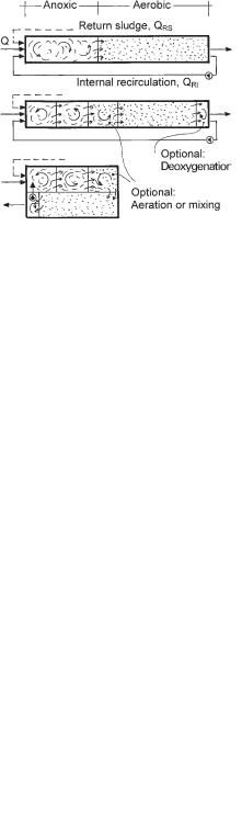
3.3.3.2 Pre-anoxic zone denitrification
The activated sludge tank is divided into two main parts, the anoxic zone and the aerobic zone. Since biodegradation of organic carbon follows first-order kinetics, the anoxic zone may be subdivided (Fig. 3.16). Furthermore. the last one or two anoxic compartments may also be equipped with aeration installations, for flexibility.
The aeration tank may have any configuration, as shown in Section 3.3.1. Since it is often difficult to keep the dissolved oxygen concentration in the outlet zone as low as desired, a final nonaerated zone, from which the internal recirculation flow is
Fig. 3.16 Pre-anoxic zone denitrification tank configurations.

3.3 Plant Configurations 103
withdrawn, may be appropriate. If the tank is arranged in a U-shape, the recycling pump merely has to push the flow through the dividing wall.
The hydraulic head loss along such activated sludge tanks is in the range of centimeters if the top of the dividing walls end 0.10–0.30 m below the water level.
The internal recycling flow (QIR) at municipal treatment plants is in the range of 3–5 Q, depending on the wastewater strength and the effluent requirements. Since the head loss is small, it is hard to size the recycling pump, therefore, a variablespeed drive to adjust the flow is appropriate. The total recycle flow (QR) is defined with Eq. 36:
QR = QRS + QIR |
(36) |
If one assumes no nitrification in the anoxic zone, no denitrification in the aerobic zone, and no nitrate in the effluent from the anoxic zone, the required flow to be recirculated can be calculated by mass balance (Eq. 37), and the denitrification efficiency is obtained with Eq. 38 which are derived as follows:
Q · SNH4,N = (Q + QR) · SNO3,e |
|
||||||||
|
SNO3,e |
= |
|
1 |
|
|
|
(37) |
|
|
|
1 + QR/Q |
|
||||||
|
SNH4,N |
|
|
|
|||||
çN = |
SNH4,N – SNO3,e |
= 1 – |
1 |
(38) |
|||||
|
|
|
|
1 + QR/Q |
|||||
|
|
|
|
SNH4,N |
|
||||
Eq. 37 indicates that, if a low effluent nitrate concentration is required at a high influent concentration and consequently a high concentration of nitrate must be denitrified, the recycling ratio (QR/Q) must be high. Since not only nitrate but also dissolved oxygen is transferred to the anoxic zone via the recycled flow, some organic carbon is removed aerobically and thus is lost for denitrification.
Process control may be limited to automatic control of the aeration intensity, to maintain a preset dissolved oxygen concentration. If monitors for ammonia and nitrate are installed at the aeration tank outlet or – even better – at the outlet of a group of aeration tanks, the signals can be used for additional control measures, the purposes of which may be:
•Saving energy: If the concentration of ammonia is zero and that of nitrate is in the desired range, aeration of the denitrification cells can be switched off or, if they are already off, the set-point for aeration control can be lowered. If ammonia increases the opposite measures have to be taken.
•Keeping ammonia low in the winter: If at very low temperatures of the mixed liquor the concentration of ammonia increases, one might try to improve nitrification by raising the set-point for aeration control above the usual 1.5–2.0 mg L–1 of dissolved oxygen. This was successful at some plants.
•Improving nitrate removal: If the concentration of ammonia is about zero but the concentration of nitrate is at its upper limit, aeration in the denitrification cells can be stopped and/or the internal recycling flow can be increased.
104 3 Activated Sludge Process
Numerous large municipalities in Germany, including Berlin, Stuttgart, and Bremen, and also smaller cities are using single-stage activated sludge plants that implement the pre-anoxic zone denitrification process.
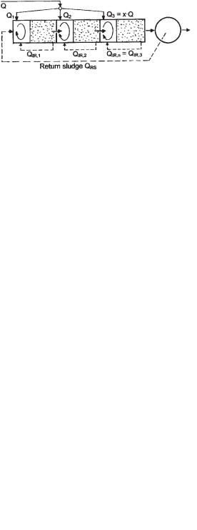
3.3.3.3 Step-feed denitrification process
The activated sludge tank in the step-feed denitrification process consists of two to three pre-anoxic zone units in series: the return sludge is diverted to the first denitrification zone and the wastewater is distributed to each denitrification zone (Fig. 3.17). Although the first experiments on this process were performed in the UK [58] and later in Japan [59], the first results for a full-scale plant were reported by Schlegel [60] in Germany.
Again, considering complete nitrification in the aeration zones and complete denitrification in the anoxic zones, the effluent nitrate concentration for the last denitrification zone can be calculated by mass balance (Eq. 39):
(x · Q) · SNH4,N = (Q + QRS + QIR,n) · SNO3,e |
(39) |
The flow (x Q) is the fraction of the total wastewater flow entering the last denitrification zone, and x must not be equal to the inverse number of units.
|
SNO3,e |
= |
x |
|
(40) |
||
|
1 + (QRS/QIR,n)/Q |
||||||
|
SNH4,N |
|
|||||
çN = 1 – |
|
x |
(41) |
||||
|
|
|
|||||
1 + (QRS + QIR,n)/Q |
|||||||
|
|
|
|
||||
To increase nitrate removal in the step-feed process, it is necessary to decrease the fraction of wastewater diverted to the last denitrification zone (decrease x) or to increase the return sludge flow and/or the internal recirculation of the last unit (QIR,n) (Eqs. 40 and 41). In existing plants, however, internal recirculation is generally not used with the step-feed process. Since increasing the return sludge flow (QRS) can hinder the final clarification, it seems more appropriate to decrease x. This is possible only if the organic carbon contained in the wastewater flow (x Q) is sufficient to denitrify the incoming nitrate load.
Due to the stepwise ‘dilution’ of the return sludge with wastewater, the MLSS drops from unit to unit. The result is a higher average concentration of MLSS than
Fig. 3.17 Step-feed denitrification tank configuration.
3.3 Plant Configurations 105
in the effluent of the last aeration tank. This is considered an advantage, since the MLSS of the effluent determines the size of the final clarifiers. To maintain the same loading rates in the three compartments it is possible to chose appropriate tank volumes or, which is easier, to distribute the wastewater flow appropriately. This would occur when Q1 = 0.4 Q, Q2 = 0.33 Q, and Q3 = 0.27 Q. The MLSS would then be, respectively, 4.3 kg m–3, 3.5 kg m–3, and 3.0 kg m–3. Without internal recirculation, the ratio CCOD/SNO3, which determines the degree of nitrate removal, in the three denitrification zones differs considerably. With QIR,1 = 1.0–1.5 Q, QIR,2 = 0.4–0.5 Q, and QIR,3 = 0, CCOD/SNO3 takes the same value. In the three-step process with QRS = Q, QIR,3 = 0, and x = 0.27, the denitrification efficiency is 86% (Eq. 41). If with more-concentrated wastewater a low nitrate concentration must be maintained, QIR,3 (Eq. 41) has to be selected. QIR,1 and QIR,2 then have to be increased appropriately.
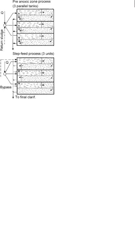
The similarity of the pre-anoxic zone denitrification process and the step-feed process is obvious when Eqs. 38 and 41 are compared. To achieve 86% denitrification efficiency in the pre-anoxic zone process, the recycling ratio must be QR/Q = 6.4. The differences between the pre-anoxic zone process and the step-feed process are illustrated in Figure 3.18.
The advantages of the pre-anoxic zone process are that each of the three tanks is operated independently and that the tanks all have the same water level and depth. In the step-feed process some head loss occurs as the water flows from one tank to the next; therefore, either the water depth differs from tank to tank (same bottom
Fig. 3.18 Comparison of step-feed and pre-anoxic zone processes.
106 3 Activated Sludge Process
level) or the water depth is kept constant (different bottom levels). For maintenance, it is necessary to have a bypass for each tank in the step-feed process.
In both processes, dissolved oxygen that enters the denitrification zone removes organic carbon and hence decreases denitrification. Therefore, non-aerated outlet zones are shown in the pre-anoxic zone tanks. In the step-feed process only the first and second aeration tanks may be equipped with a non-aerated zone.
Several plants with the step-feed process are operated by the Emschergenossenschaft and, e.g., the cities of Wolfsburg and Bremerhaven.
3.3.3.4 Simultaneous nitrification and denitrification
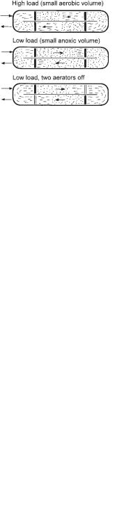
The key to nitrogen removal by the simultaneous nitrification–denitrification process is to appropriately set the aerators so as to establish sufficiently large aerobic and anoxic zones simultaneously (Fig. 3.19). Since the load of any wastewater treatment plant fluctuates diurnally, the concentrations of nitrate and ammonia vary inversely when the aerator setting is constant. To achieve the desired nitrogen removal, a process control is therefore required.
Pasveer in 1964 [16] was the first to report on simultaneous denitrification in an oxidation ditch. He achieved this by setting the optimal immersion depth of the surface aerator so as to create a sufficiently large anoxic zone. At the Vienna Blumenta plant (Section 3.1.3), the oxygen uptake rate was continuously measured with a special (homemade) respirometer. The respirometer output was used to switch the appropriate number of aerators to achieve the desired nitrogen removal [61].
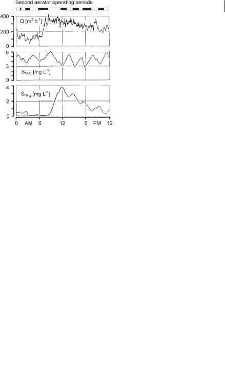
The first real process control for simultaneous denitrification was developed by Ermel [62]. A continuous sample flow was separated from the mixed liquor by ultrafiltration and diverted to a nitrate monitor. At the Salzgitter Bad plant the two closed-loop aeration tanks are operated in parallel. Each tank is equipped with three mammoth rotor surface aerators. One rotor in each tank is operated continuously to create sufficient circulating flow. The two other rotors of each tank are automatically switched on if the nitrate concentration in the sample flow drops to, e.g., SNO3 = 3 mg L–1. The aerators were stopped if, e.g., SNO3 reached 6 mg L–1 and were switched on again after the set point of SNO3 = 3 mg L–1 was reached. Figure 3.20 shows a daily time course of ammonia and nitrate levels measured in one of the aer-
Fig. 3.19 Simultaneous nitrification and denitrification under different loading conditions.
3.3 Plant Configurations 107
ation tanks. Due to the still-low denitrification rate during the period of high ammonia load (8 to 12 AM) the concentration of ammonia rises to about 4 mg L–1 N. As the denitrification rate increases after noon, the off-periods of the two aerators become shorter and the ammonia concentration decreases.
A more sophisticated control system based on monitoring both nitrate and ammonia was used in the wastewater treatment plant in Hildesheim [63].
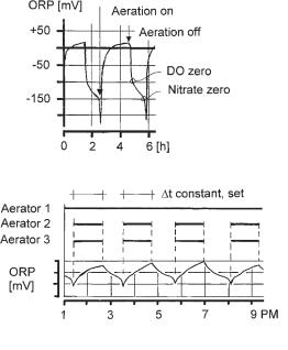
In Salzgitter Bad an ORP controller was tested as a very simple, low-cost control method. Since the oxidation–reduction potential (ORP) drops sharply, if at zero DO nitrate reaches zero, the controller switches the additional aerators on at a certain slope of ORP. The additional aerators are then operated for a preset period of time. Figure 3.21 shows the time course of ORP. The effluent during the time when the ORP controller was used was as good as when the nitrate controller was used [64]. At about the same time, similar experiments with ORP were conducted in Canada [65].
Some newer plants for simultaneous nitrification and denitrification are equipped with propellers (in addition to surface aerators) to maintain a sufficient flow velocity independent of the number of aerators in operation. Such plants can also be operated in intermittent nitrification–denitrification mode.
In addition to the cities already mentioned, plants with simultaneous nitrifica- tion–denitrification are also operated in, e.g., Osnabrück, Münster, Gera, Paderborn, Tel-Aviv, and in numerous smaller communities in which oxidation ditches were converted to the simultaneous mode by means of automatic control.
Whether and how much of the readily biodegradable organics are oxidized by dissolved oxygen (and therefore lost for denitrification) depend on the placement of the wastewater inlet and its distance to the next aerator. It is advisable to introduce the flow near the tank bottom, since anoxic conditions are predominant there.
The closed-loop circulating flow tanks for simultaneous nitrification–denitrifica- tion can be regarded as completely mixed. In addition, due to the high dilution of
Fig. 3.20 Time courses of ammonia and nitrate levels in one aeration tank at the Salzgitter Bad plant.
108 3 Activated Sludge Process
Fig. 3.21 ORP to control simultaneous denitrification. Top: with intermittent aeration, showing the important points; bottom, denitrification control at the Salzgitter Bad plant.
the incoming wastewater by the circulating flow, conditions favorable for filamentous bacterial growth are established. If the wastewater contains a higher fraction of readily biodegradable organics, a selector or an anaerobic mixing tank for enhanced biological phosphate removal is recommended.
3.3.3.5 Intermittent nitrification–Denitrification process
Aeration tanks for intermittent nitrification–denitrification must be equipped with an aeration system and mixing devices. The design of the aeration system has to take into consideration the aeration-off periods. To improve the aeration efficiency of plants with diffused air aeration, it may be advisable to also operate the propellers during the aeration periods.
In intermittent nitrification–denitrification plants the fraction of readily biodegradable organics, which enters the tank while aeration is operating, may be oxidized by dissolved oxygen and therefore lost for denitrification. This must be considered when calculating the nitrate to be denitrified. Precautions against the growth of filamentous organisms should be taken, because the tanks are completely mixed.
The duration of the aeration periods and the aeration-off periods can be set with a timer. Any other control system described in Section 3.3.3.4 can be used to achieve a more stable effluent quality. In Germany, especially in the large number of extended aeration plants, an ORP controller is frequently used. NitraReg is another low-cost control system, which requires only continuous measurement of the dissolved oxygen concentration [66]. By knowing the oxygen transfer capacity, the oxygen uptake rate is automatically calculated and used as the control parameter.
3.3 Plant Configurations 109
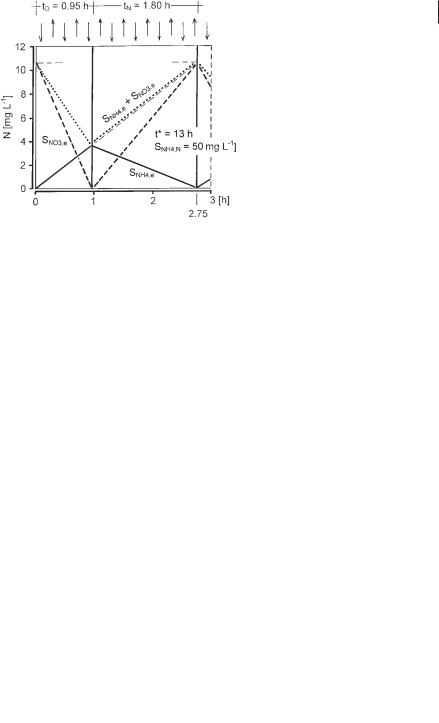
The time course of nitrate concentration during the anoxic period (tD) depends on the activity of the denitrifiers, and the time courses of ammonia and nitrate levels during the aerobic period (tN) depend on the activity of the nitrifiers. Since the reactor is completely mixed, the time course of ammonia concentration during the anoxic period can be constructed with Eq. 42.
SNH4,t = SNH4,N · [1 – exp (–t/t*)] |
(42) |
Neglecting the effluent loss of ammonia during the anoxic period, a straight line shows how ammonia would increase (Eq. 43).
SNH4,t = SNH4,N · (t/t*) |
(43) |
The deviation between Eqs. 42 and 43 is <5% if tD/t* is below 0.25, which is true in practice in activated sludge plants. Figure 3.22 therefore shows only the straight line calculated according to Eq. 43. Since ammonia is converted to nitrate during the aerobic period, the nitrate concentration at the end of a cycle is the starting concentration for the anoxic period of the next cycle.
The average effluent concentration of nitrogen (SNO3,e + SNH4,e) can be derived from Figure 3.22, to obtain Eq. 44:
SNO3,e |
+ SNH4,e |
= 0.5 · SNH4,N |
· |
2 · tD |
+ tN |
(44) |
t* |
|
|||||
|
|
|
|
|
|
The efficiency of nitrogen removal can be calculated with Eq. 45:
çN = |
SNH4,N – (SNH4,e + SNO3,e) |
= 1 – |
tD + 0.5 · tN |
(45) |
|
t* |
|||
|
SNH4,N |
|
||
Fig. 3.22 Time courses of ammonia and nitrate levels during intermittent nitrification and denitrification.