


4
Reagent Jetting Based Deposition Technologies for Array Construction
Mitchel J. Doktycz
4.1 Introduction
Technologies utilizing arrayed biological reagents are revolutionizing bioanalytical measurements. In genomics, initial successes in gene microarray experiments for analysis of gene transcription have led to applications involving microarrays of proteins [1, 2], whole cells [3], membranes [4] and small molecules [5]. High throughput screening applications, which exploit small volume reaction mixtures, are also leveraging o of microarray technology. Deposition technologies have developed to meet the challenges inherent to these various applications and materials. Deposition technologies must be compatible with the assay requirements (e.g. reagent conservation, volume metering, array density) and bridge ‘macro–scale’ sample containers to microscale assay devices.
Two robust technologies are becoming conventional. Currently, most microarraying of prepared reagents is carried out using pin based, touch–o deposition techniques, which is the subject of the following chapter in this book. This technique is inherently simple and numerous variants of pin spotting are in practice or development. Another approach with gaining popularity is based on reagent jetting. Similar to ink jetting technology that is commonly used in desktop printers, reagent jetting does not require contact between the dispensing tip and surface and allows for metering of extremely small volumes of reagent. This latter technique will be overviewed herein, highlighting variants and their specific strengths.
4.2 Reagent Jetting – Technology Overview
Various approaches to reagent jetting are currently in use. These techniques borrow features and technology developed for commonly used ink jet based desktop printers [6]. These printers are typically drop–on–demand devices that
64 Mitchel J. Doktycz
use either thermal or piezo based actuation mechanisms (Fig. 4.1). The development of mass-marketed printing devices over the past several decades has facilitated the use of this technology for other purposes, including biomedical applications, solder dispensing, construction of three–dimensional ceramic structures and construction of organic-based electronic circuits [7]. Another class of reagent jetting devices is based on a high-speed solenoid valve. This latter technique is typically used for industrial applications, such as bar code printing or container labelling, and is becoming popular in liquid handling instruments.
A key strength of reagent jetting techniques is the ability to rapidly dispense extremely small volumes (picoliter level) of liquid. When compared to touch–o spotting techniques, reagent jetting is a gentle deposition technique, enabling printing on fragile substrates, and can allow for volume metering (discussed further below). General limitations of the technique are its complexity, relative to pin printing, and e ective operation occurs within a pre-designed range of physical and chemical parameters. Selection of a particular reagent jetting technique depends on the intended application. Specific advantages and disadvantages of di erent reagent jetting techniques are discussed in the relevant sections below.
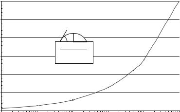
A general consideration is the relation between a dispensed volume and the resultant spot size. Using a hemispherical cap as a model for a sessile drop on a flat surface leads to the following relation between spot size (radius, r) and volume (V ):
V = (3b + b3)πr3/6 |
(4.1) |
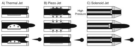
Fig. 4.1. Reagent jetting techniques: Cross sectional view of the fluid channel and nozzle, illustrating the mechanism of droplet ejection, for three di erent reagent dispensing techniques is shown. Thermal-based jets (a) operate by rapidly heating and cooling the reagent, which results in ejection of a droplet. Piezo-based techniques
(b) employ rapid expansion and contraction of the piezo material to cause droplet ejection. Solenoid based jets (c) function by rapidly opening and closing a valve that controls the flow of a pressurized reagent
4 Reagent Jetting Based Deposition Technologies for Array Construction |
65 |
|
1200 |
|
|
|
|
|
|
1000 |
|
|
|
|
|
|
|
|
|
|
|
|
|
|
|
|
|
|
|
ns) |
800 |
|
|
|
|
|
icro |
|
|
|
|
|
|
|
|
|
|
|
|
|
r (m |
|
|
|
|
|
|
te |
600 |
|
|
|
|
|
e |
|
|
|
|
|
|
t Diam |
|
|
|
|
|
|
ulated Spo |
400 |
|
|
|
|
|
200 |
|
|
|
|
|
|
Calc |
|
|
|
|
|
|
|
|
|
|
|
|
|
|
0 |
|
|
|
|
|
|
0.001 |
0.01 |
0.1 |
1 |
10 |
100 |
|
|
|
Sample Volume (nl) |
|
|
|
Fig. 4.2. Predicted relation between dispensed volume and spot size: The calculated spot sizes are determined based on the dispensed volume and the contact angle formed between the surface and liquid as shown in the inset drawing
where b is the ratio between the height and radius of the sessile drop. This value can be related to the contact angle that the droplet makes with the surface. These parameters are pictorially described in Fig. 4.2. Also shown in Fig. 4.2 is a graph of this relation using a contact angle of 40◦ (such as occurs between water and a poly–L–lysine treated glass surface). The graph shows the relation between spot diameter and dispensed volume. Approximately an order of magnitude lowering in volume is required to drop the spot diameter in half, and picoliter scale volumes are therefore required for spot diameters on the order of a few tens of microns. Such volumes are in line with reagent jet dispensing. For example, a 1200 dpi printer corresponds to spot diameters on the order of 20 m. Alternatively, to achieve small spots, the contact angle must be increased. Although this variable is not easily changed, welled structures can be used to demarcate the deposition area. This requires careful alignment between the dispenser and the target substrate, which can be challenging when dealing with structures on the order of a few tens of microns. This relation between volume and spot size highlights one of the major challenges for employing any liquid dispensing technique for further miniaturization of arrays.
4.3 Thermal Jet Based Dispensing
Thermal jets, often referred to as bubble jets, eject droplets by superheating a small volume of liquid near the dispensing orifice (Fig. 4.1a). Typically, a re-
66 Mitchel J. Doktycz
sistive heating element is controlled such that the application of current causes rapid heating of the ink. This generates a vapor bubble, forcing liquid from the nozzle (middle panel, Fig. 4.1a). Upon cooling, the bubble collapses, pinching the liquid stream and allowing for the channel to refill (lower panel, Fig. 4.1a). Heating and cooling can occur very quickly, with repetition rates greater than 10,000 Hz being typical. Considering the simplicity of the required structure, which consists of a liquid channel, nozzle and heating element, thermal jets can be fabricated at high density using techniques developed in the semiconductor industry. The simple manufacturing process coupled with the high demand for desktop printers have led to low cost, disposable print heads.
A significant di erence between desktop printers and those needed for high throughput screening applications is the number of ‘inks’ required. The few ink cartridges needed for color printing pales in comparison to the thousands of reagents used to create a cDNA microarray. This necessitates cleaning and refilling of the ink cartridges. A further complication is the ink formulation. Commercial printers are optimized for specific ink compositions and printing densities. Factors such as surface tension and viscosity must be carefully controlled. Further, these inks are often matched with the properties of the print media for optimal performance. Similar considerations are necessary for adopting thermal jet based printing for biomedical applications. To date, custom thermal jet print heads, specifically designed for microarray printing, have not been described. Nevertheless, several examples on the use of commercial printers, adapted to printing biomaterials, have been published [8–10].
To adapt a commercial printer for dispensing DNA or protein solutions, the ink cartridge must be carefully rinsed out and replaced with the biochemical in a solution of similar viscosity and surface tension as the original ink. This can be done by the addition of various reagents such as ethanol [8], glycerol [9] or a detergent such as sodium dodecyl sulfate [10]. The printed spots can be extremely small, on the order of a few tens of microns, which is consistent with the dispensed volume of a few tens of picoliters. The rapid heating, which can reach temperatures of 200–300◦C, could presumably cause protein degradation which would lead to low protein activity as well as clogging of the nozzle. However, while extensive evaluation of di erent proteins has not been performed, the problem of protein denaturation does not appear to be significant. This is likely due to the highly localized heating which expands the liquid behind the ejected droplet. When spotting nucleic acids, the potential for denaturation may be advantageous because single stranded probes are desired.
While the use of a commercial printer for printing biomolecules takes advantage of low instrumentation costs and exploits various computer software programs for defining the printed regions, there are no simple means for changing reagents and complete recovery of unused material is not possible. Therefore, such an approach is only useful for applications where one, or a few reagents, need to be patterned.
4 Reagent Jetting Based Deposition Technologies for Array Construction |
67 |
4.4 Piezo Jet Based Dispensing
This technology operates by mechanically inducing a pressure wave into the liquid. Rapid dimensional changes of a piezoelectric material can induce this pressure pulse to eject a single droplet (Fig. 4.1b). A number of di erent designs are employed in desktop printers, with the piezoelectric material operating in either a push, pull, shear or squeeze tube mode [6]. The characteristics of the droplet are dependent on a number of factors including the physical and chemical characteristics of the liquid, the nozzle structure and the dimensions of the preceding fluidic chamber. Commercial desktop printers employ dozens to hundreds of individually controlled dispensers. In contrast to thermal jet printers, single channel piezo-based dispensers are commercially available for applications other than desktop printing. Instruments or components from manufacturers such as MicroFab Technologies [11], Microdrop GmbH [12], and Perkin Elmer Life Sciences [13] are commonly used for biomedical applications. Perkin Elmer’s Packard BioChip ArrayerTM and SpotArrayTM Enterprise are specifically designed for microarray construction.
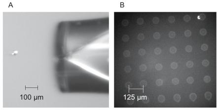
The majority of dispensers for research applications are based on the squeeze tube design. Typically, a glass capillary is mounted inside a cylindrical piezo material. A specific voltage pulse is applied to the piezo material to create the pressure pulse. The optimal duration and amplitude of the voltage depends on the design of the device. Typically, the diameter of the dispensed droplet matches closely the diameter of the orifice. Volumes of a few picoliters are reproducibly dispensed at rates of a few thousand per second. Figure 4.3a displays an 10 pl drop being dispensed from a 20 m orifice. The image in Fig. 4.3a is actually a composite of 15 dispenses captured with a synchronized Xenon strobe lamp and illustrates the reproducibility of the technique. The spots that are formed from a single dispense are on the order of 50 m in diameter (Fig. 4.3b). The Packard BioChip ArrayerTM uses a 75 m nozzle and dispenses drops on the order of 300 pl. This leads to spots on the order of 200–300 m when dispensing onto a glass slide [13]. These volumes and resultant spot sizes are consistent with the estimates displayed in Fig. 4.2.
The sub–nanoliter volumes that can be dispensed and the commercial availability of the technology are clear strengths of the piezo jetting technique. However, a complication is that the dispense nozzle must be filled with the desired reagent and a specific fluid pressure must be maintained for dispensing. Appropriate pressure in the fluid tube is necessary for preventing the reagent from dripping out the nozzle and for optimal performance of the device. One method, aspirating sample through the nozzle, requires su cient time to stabilize the system pressure and can reduce fluid handling throughput. Further, small nozzle diameters can lead to clogging and slow aspiration rates. Alternatively, the dispenser can be dedicated to delivering a particular reagent by filling from a reservoir behind the nozzle, much like in a conventional desktop printer cartridge.
68 Mitchel J. Doktycz
Fig. 4.3. Piezo-based reagent jetting: (a) composite image of a droplet ejecting from 20 m nozzle (MicroFab, Inc.). The volume droplet is on the order of 10 pl. (b) shows the array that results from individual dispenses
Considering the capabilities of piezo jet dispensing, many applications are under development [11]. For example, microarraying of previously prepared DNA probes is competitive with pin based deposition techniques, especially when many dispensing tips are used in parallel. Additionally, in situ construction of high density oligonucleotide microarrays appears to be a viable technique [14]. This application involves an array of piezo jets operating in a dispense mode. Each dispenser delivers a unique reagent required in the phosphoramidite-based synthesis of DNA oligomers [15]. By defining the location of individual dispenses, large arrays of long oligonucleotides (e.g. 60–mers) of designed sequence can be constructed at high density. Other applications, such as in high throughput screening of pharmaceutical compounds, have also been considered [16]. The small volumes that can be dispensed are ideal for economical evaluation of large numbers of samples.
4.5 Solenoid Jet Based Dispensing
A third commonly used reagent jetting technique is fundamentally di erent from the other two. The thermaland piezo-based reagent jetting techniques function as fluid pumps. The solenoid-based technique exploits high speed valves. In operation, the valve is positioned between a pressurized fluid source and a nozzle (Fig. 4.1c). Rapid actuation of the valve causes fluid to stream from the nozzle. High speed miniaturized solenoid valves are available from the Lee Company (Westbrook, CT). These valves can open and close as often as 1200 Hz under pressure heads on the order of 10 psi. To operate at these rates, a voltage ‘spike’ ( 40V), as short as 150 microseconds, is applied to
4 Reagent Jetting Based Deposition Technologies for Array Construction |
69 |
rapidly open the valve. The valve can then be held open for longer pulses, or indefinitely, using a lower ‘hold’ voltage ( 8 V).
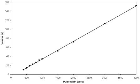
An advantage of this approach to reagent jetting is the ability to precisely meter nanoliter–scale volumes of fluid. Typical syringe pump based liquid handling instruments operate in the microliter to milliliter range and are inappropriate for arraying or high throughput applications at smaller volumes. Conversely, the picoliter scale quantities dispensed with thermal or piezobased techniques are too small to e ectively deliver volumes in the nanoliter range. To increase or alter the delivery volume using these techniques, multiple dispenses are necessary. Even at high actuation rates, such an approach is too time consuming [16]. With solenoid-based dispensers, volumes ranging from a few nanoliters to several microliters can be rapidly delivered [17]. Flow through the valve is dependent on a number of parameters, including the applied pressure, valve opening time, fluid viscosity, and nozzle dimensions. The valve opening time is the easiest variable to control and can be modulated by simply changing the duration of the hold voltage. The linear relation between dispensed volume and valve opening time is shown in Fig. 4.4.
Several fluid dispensing devices based on solenoid valve technology have been described [17–19]. The technology is relatively simple to implement, enabling the construction of custom instruments for desired applications. Commercial systems based on solenoid valve technology are available from Carte-
Fig. 4.4. Graph of the volume ejected as a function of valve pulse width for a solenoid-based reagent jet. A linear relation between the dispensed volume and valve opening time is observed. A pressure head of 10 psi and a nozzle of 125 m inner diameter was used. The volumes were determined by weighing the sum of 1000 dispensing events
70 Mitchel J. Doktycz
sian Engineering and Innovadyne Technologies. Cartesian produces a complete system, containing motion control and fluid handling. This system uses a finely controlled syringe pump for aspiration and for maintaining a desired hydraulic pressure when dispensing. Incremental steps of the syringe pump are timed relative to the solenoid valve opening to dispense reagents.
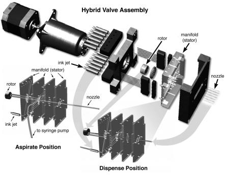
Innovadyne Technologies, Inc. manufactures ASAPTM technology and is integrated into di erent commercial liquid handling platforms. At the heart of Innovadyne’s technology is a ‘hybrid valve’ structure that controls the fluidic connectivity for performing di erent operations. An expanded view of the valve is shown in Fig. 4.5. The switching valve is a flat face configuration, similar to that found in conventional high performance liquid chromatography applications. The face of the rotor is grooved and pressed against the stator face. The stator contains fluid ports that connect to the various components via a microfluidics structure. Turning the rotor changes the fluid paths based on the design of the grooved surface. A stepper motor performs the rotation and the actuator body applies pressure to the face of the stator to prevent
Fig. 4.5. Expanded drawing of the hybrid valve: The individual components of the hybrid valve are illustrated. In operation, a stepper motor turns the rotor through the actuator body. The position of the rotor, relative to the manifold (stator), determines the fluid pathway. The fluid pathways for the aspirate and dispense positions are shown (Reprinted with permission from Innovadyne Technologies)
4 Reagent Jetting Based Deposition Technologies for Array Construction |
71 |
leakage. With this set up, multiple fluid streams can be switched simultaneously and rapidly. Further, multiple functionalities can be integrated without interfering in the sample path. This prevents contamination of the solenoid valve that can reduce its operational lifetime. Additionally, di erent components such as syringe pumps, washing and purging sources, or reagent sources can be integrated depending on the application. The hybrid valve can deliver greater than 200 individual dispenses per minute and deliver volumes ranging from 50 nl to 10 l with less than 5% coe cient of variation.
Several applications based on solenoid-based reagent jetting have been developed. Although the system can be used for microarraying, the typical lower limit on droplet volume ( 1 nl) is too large to produce high density microarrays. Other applications exploit the technique’s ability to rapidly dispense a desired volume. These applications include high throughput screening of pharmaceutical candidates or synthesis of combinatorial libraries [18]. When used as a reagent dispenser, care must be taken not to expose the valve to harsh solvents as this can lead to degradation of the valve seals. The use of solenoid-based reagent dispensing has also been described for the automated screening of protein crystallization parameters [19]. The ability to dispense on the nanoliter scale, a orded by solenoid-based reagent jets, allows significant miniaturization and higher throughput leading to significant cost savings.
References
1.Le HP 1998. Progress and Trends in Ink–jet Printing Technology. J of Imaging Science and Technology 42(1):49–62
2.Bateman TA, Ayers RA and Greenway RB (1999) An Engineering Evaluation of Four Fluid Transfer Devices for Automated 384–Well High Throughput Screening. Lab Robotics and Automation 11:250–259
3.Mueller U, Nyarsik L, Horn M, Rauth H, Przewieslik T, Saenger W, Lehrach H, Eickho H (2001) Development of a technology for automation and miniaturization of protein crystallization. Journal of Biotechnology 85, 7–14
4.Okamoto T, Suzuki T and Yamamoto M (2000) Microarray Fabrication with Covalent Attachment of DNA Using Bubble Jet Technology. Nature Biotechnology 18:438–441
5.Schober A, G¨unther R, Schwienhorst A, D¨oring M, and Lindmann BF (1993) Accurate High–Speed Liquid Handling of Very Small Biological Samples. BioTechniques 15(2):324–329
6.Roda A, Guardigli M, Russo C, Pasini P and Baraldini M (2000) Protein Microdeposition Using A Conventional Ink–Jet Printer. BioTechniques 28(3):492– 496
7.Lahiri J, Jonas SJ, Frutos AG, Kalal P and Fang Y (2001) Lipid Microarrays. Biomedical Microdevices 3(2):157–164
8.de Wildt RM, Mundy CR, Gorick BD and Tomlinson IM (2000) Antibody arrays for high–throughput screening of antibody–antigen interactions. Nature Biotechnology 18:989–994
72Mitchel J. Doktycz
9.Hughes TR, M Mao M, AR Jones AR, J Burchard J, MJ Marton MJ, KW Shannon KW, SM Lefkowitz SM, M Ziman M, JM Schelter JM, Meyer MR, Kobayashi S, Davis C, Dai H, He YD, Stephaniants SB, Cavet G, Walker WL, West A, Co ey E, Shoemaker DD, Stoughton R, Blanchard AP, Friend SH, and Linsley PS (2001) Expression profiling using microarrays fabricated by an ink–jet oligonucleotide synthesizer. Nature Biotechnology 19:342–347
10.Hicks JS, Harker BW, Beattie KL, and Doktycz M J (2001) Modification of an automated liquid handling system for reagent–jet, nanoliter–level dispensing. Biotechniques, 30 (4), 878–885
11.MacBeath G and Schreiber SL (2000) Printing Proteins as Microarrays for High–Throughput Function Determination. Science 289:1760–1763
12.Lemmo AV, Fisher JT, Geysen HM, and Rose DJ (1997) Characterization of an Inkjet Chemical Microdispenser for Combinatorial Library Synthesis. Anal. Chem. 69:543–551
13.Blanchard AP, Kaiser RJ, and Hood LE (1996) High–Density Oligonucleotide Arrays. Biosensors & Bioelectronics 11(6/7):687–690
14.Allain LR, Askari M, Stokes DL, Vo-Dinh T (2001) Microarray sampling– platform fabrication using bubble–jet technology for a biochip system. Fresenius J Anal Chem 371:146–150
15.Uetz P, Giot L, Cagney G, Mansfield TA, Judson RS, Knight JR, Lockshon D, Narayan V, Srinivasan M, Pochart P, Qureshi-Emili A, Li Y, Godwin B, Conover D, Kalbfleisch T, Vijayadamodar G, Yang M, Johnston M, Fields S, Rothberg JM (2000) A comprehensive analysis of protein–protein interactions in Saccharomyces cerevisiae. Nature 403:623–627
16.Qureshi-Emili A and Cagney G (2000) Large–scale functional analysis using peptide or protein arrays. Nature Biotechnology 18:393–397
17.Calvert P (2001) Inkjet Printing for Materials and Devices. Chem. Mater. 13:3299–3305
18.Cooley P, Wallace D, Antohe B (2001) Proceedings, SPIE Conference on Microfludics and BioMEMS. Vol. 4560, p. 177–188, Microfluidics and BioMEMS, Carlos H Mastrangelo; Holger Becker; Ed
19.Papen R, Croker K, and Kolb A (1998) Nanoliter Dispensing Technology. Genetic Engineering News, 18(4)