

Biomedical EPR Part-B Methodology Instrumentation and Dynamics - Sandra R. Eaton
.pdfLOOP-GAP RESONATORS |
39 |
For a critically coupled resonator,  and for an overcoupled resonator
The fraction of incident power transmitted to the sample in the resonator is given by
For example, using typical values for a |
cavity overcoupled from |
||
to Q = 1408, so |
then 0.66 of the incident power enters the |
||
resonator. Therefore, |
times the |
for the |
critically coupled |
cavity. The power, |
required to produce a given |
in an overcoupled |
|
resonator relative to that required for a critically coupled resonator is given by
When the quality factor is reduced from  resonator the power required to produce a given
by adding loss to the  will increase by the
Thus, for large  there is a potential for using only half as much power in the overcoupled resonator case relative to that required for the same Q in the inherently low Q resonator. The pulsed EPR signal for a given
  and Q is higher if the Q was achieved by overcoupling from
  than if the Q was achieved by higher loss in the resonator (due to different materials of construction, or a lossy sample). The relative signal amplitudes for the overcoupled and inherently low-Q cases are given by
and
40 |
GEORGE A. RINARD AND GARETH R. EATON |
respectively. In the limit, the overcoupled resonator yields  times the signal voltage of the inherently low-Q resonator. Experimental confirmation of these predictions is in (Rinard et al., 1994).
10.SELECTION OF THE Q OF A LGR
As discussed above, it is usually better to construct the LGR with the highest possible Q for a given desired resonator size, which means using high-conductivity materials, and overcoupling it to achieve low Q for FID and ESE measurements, rather than purposefully constructing a LGR with low Q. However, the reflected power due to overcoupling might cause a problem in some spectrometer systems. Also if the spectrometer is powerlimited, there may be an incentive to maximize the resonator Q. This may determine whether or not to use overcoupling and what degree of overcoupling would be needed. However, it is usually desirable to design the spectrometer to use an overcoupled resonator (Rinard et al., 1994). In general, one needs to reduce the dead time by decreasing Q, especially for samples with short  However, the largest Q should be used consistent with the bandwidth, the dead time, and S/N. There will be an optimum Q that gives the best S/N, but this may not be the best Q for obtaining desired information in a particular experiment, as discussed above.
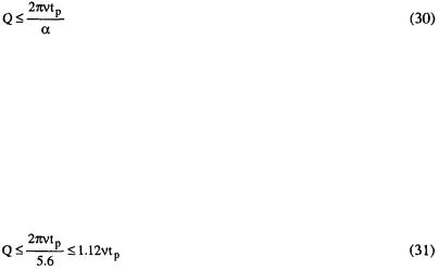
Another consideration of the Q to be selected is the pulse length. Mims (1965, 1972) matched the half-power bandwidth of the resonator with the half-power width of the Fourier transform of a pulse, yielding
where  is the width of the pulse between half amplitude points.
For a Gaussian time pulse, the width of which is measured at the half amplitude points,  For an isosceles triangular pulse, measured at half amplitude points,
  Today’s technology allows generation of very rectangular pulses on the order of tens of nanoseconds long. For a rectangular pulse,
  (Mims reported 6.6, which must have been a typo). For rough estimates to guide setting up an experiment, use of a value of 4 for short pulses and 6 for long pulses is a reasonable approximation.
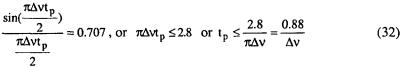
Using  Mims’ criterion for rectangular pulses becomes,
LOOP-GAP RESONATORS |
41 |
This result specifies the Q necessary to pass the frequency spectrum of the pulse. The frequency spectrum for a rectangular pulse has half power when,
where  is the bandwidth of the EPR spectra in Hertz.
For example, if it is required to excite one gauss of spectra (2.8 MHz), the resonator bandwidth should be at least  (larger for more uniform excitation). If
  from Eq. (17)
  Using these values in Eq. (31) yields
  If the pulse length,
  were 16 ns, at 9 GHz, the Q would have to be < 160 to meet the criterion of Eq. (30). The lower the frequency, the lower the Q required for a given
  For example, using
  as in the above X-band example, at 250 MHz the Q would have to be reduced to less than about 90, and a 16 ns pulse would require Q < 5. The pulse length for a given bandwidth may be any value less than that given by Eq. (32). Likewise, the Q may be any value less than that specified by Eq. (31) using the equality sign in Eq. (32). However from a practical standpoint, the dead time of the spectrometer as determined by the ring down time of the resonator will be shortest for the longest practical pulse length (lowest power pulse) and the lowest Q. There is an optimum Q above or below which the S/N will be lower, if the full spectrum is excited.
Other criteria for the choice of resonator Q include the magnitude of  needed over the frequency bandwidth, and the width of the spectrum to be studied. A pulse length short enough to provide a broad frequency spectrum to excite all the spins in the sample may require a
  for a 90-degree pulse that is unattainable in the spectrometer. This is particularly important for non-uniformly broadened samples or for imaging using magnetic field gradients. The relaxation time is also important. The pulse length,
  as calculated from setting
  spectral width, may be close to the spin relaxation time
  One should make
  to prevent the spins from relaxing excessively during excitation. Q is more important than
  for uniformly broadened samples, since the single line spectra can be excited by a pulse that is longer that that given by Eq. (32), but the Q must be low enough to faithfully reproduce the EPR spectra. It can be shown that the spectra will be very good, even if the Q is somewhat higher then that given by Eq. (31), but the comments about the optimum Q still apply. If some means for killing the Q can be utilized to shorten the resonator ring down time following the pulse, then return to the higher Q to record the EPR
42 |
GEORGE A. RINARD AND GARETH R. EATON |
signal, higher S/N may be achieved (Rinard et al., 2002a). If there were a single,  line, these criteria on Q and
  would result in an excitation bandwidth many times the line width. This is an interesting, but rather special case. More commonly, the spectrum is inhomogeneously broadened.
11.MEASURING  IN THE LGR
Measurement of the absolute value of  in a resonator is one of the more difficult tasks in EPR. Calculations, based on the details of resonator size and materials of construction, are as good as measurements in a wellcharacterized resonator. We start by discussing
  in the well-known
  rectangular cavity resonators. A large literature, cited in (Dalal et al., 1981; More et al., 1984; Poole, 1967 pp. 394-420; Eaton and Eaton, 1985; Bales and Kevan, 1970), provides confidence that the
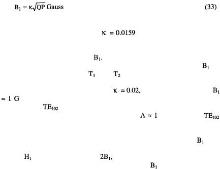
  is given by Eq. (33), where
  for a Varian
  E-231 cavity resonator.
where P is the incident power in watts and Q is the loaded Q.
Eaton and Eaton (1985) found |
as the coefficient in Eq. (33) |
for a Varian E231 cavity without |
a dewar insert. Dalal et al. (1981) |
discussed formulae for Q of a cavity and presented experimental data for the
effect of a Dewar insert on the |
Note that this is strongly dependent on |
||||
the wall thickness of the Dewar. |
The use of this relation to estimate |
for |
|||
the purpose of |
determining |
and |
from |
continuous saturation |
was |
discussed by More et al. (1984). |
|
|
|
|
|
As a convenient rule of thumb, use |
|
and with Q = 3000, then |
|||
per square root watt. Bruker cites a value of 1.4 G per square root |
|||||
watt for their |
cavity, which has a slightly higher frequency than the |
||||
Varian cavity. |
Using the notation of Eq. (19), |
for an X-band |
|
||
cavity resonator. X-band LGRs have been made with  as high as 10 (Hyde
and Froncisz, 1989). |
|
One can also use the method of perturbing spheres to measure |
with |
similar results. Note that in the formulae given in the book by Ginzton
(1957), |
is what we would call |
since the perturbing spheres method |
|
measures |
the linearly polarized |
component of |
at the position of |
measurement.
The CW continuous saturation of a well-characterized sample such as Fremy’s salt can also be used to estimate  (More et al., 1984).
LOOP-GAP RESONATORS |
43 |
When pulsed EPR is available, it is convenient to measure  in the resonator, for the exact experimental conditions of interest, by measuring the turning angle for the pulse, using Eq. (13).For example, a 40 ns pulse gives
  (assuming bandwidth is adequate). If the Q is low enough and the relaxation time is long enough (e.g., the E’ center in irradiated quartz (Eaton and Eaton, 1993), the turning angle can be used to measure
  in a critically coupled resonator also. Bimodal LGR and Crossed-loop Resonator (CLR)
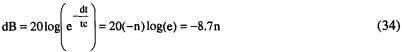
Two LGRs can be constructed so that they are orthogonal and intersect at the sample (Hyde and Froncisz, 1989; Tsapin et al., 1992). An alternative approach to orthogonality was described by Piasecki et al. (1996) for an S- band bimodal resonator. This approach uses two resonators coaxial with one another, but arranged such that the integral over all space of the fields from the two are equal to zero, instead of making the resonators locally orthogonal. The orthogonality of the two resonators has advantages for both CW and time domain EPR. For CW EPR, the source and detector are very well isolated and phase noise from the source is essentially eliminated. For time domain EPR the isolation reduces the dead time of the spectrometer. Following a high-power pulse, the power in the resonator has to decay to less than the signal power in order to observe the signal. Depending on the signal strength, this may require a change in power by ca. 140 dB or about 16 time constants (Mims 1965, page 324), or even more. A commonly cited value for NMR is 21 time constants (Gerstein and Dybowski, 1985). Isolation provided by the CLR between the pulse power and the signal resonator decreases the dead time by the amount of the isolation. Let the dead time, dt, be n power decay time constants, tc, for the resonator, dt = ntc. Then,
or 
Thus, with 60 dB isolation in the CLR, the dead time is shortened by ca. 7 resonator time constants. In addition, each LGR can be optimized and Q- switched (Rinard et al., 2002a) to improve S/N and further reduce the dead time.
It has proven difficult to extend the Piasecki et al. (1996) approach to X- band, because of the small size of critical components. Success has been achieved with the CLR design at frequencies at 250 MHz (Rinard et al.,
44 |
GEORGE A. RINARD AND GARETH R. EATON |
2002a), L-band (Rinard et al., 2000), S-band (Rinard et al., 1996a,b) and X- band (unpublished).
Preliminary tests simulating animal movement also indicates that artifact from animal movement can be greatly reduced by using a CLR.
12.VARIABLE TEMPERATURE
The commercial X-band cavity resonators typically are equipped with a Dewar that inserts into the cavity. The temperature of the sample is changed while the resonator is kept at ambient temperature. Because LGRs are smaller than cavities at the same frequency, and because the LGR is generally designed to have a large filling factor, there is not sufficient space in the sample loop for the traditional flow-through Dewar. Consequently, the entire resonator and sample assembly is cooled. In the limit, the spectrometer system performance is limited by the thermal noise of the resonator. With a cross loop resonator, it is also possible to cool the resonator and the first stage microwave amplifier to reduce thermal noise (Rinard et al., 1999b,d). In addition, in a well-designed cryostat there is less temperature gradient over the sample when the entire assembly is cooled. However, it is much more complicated to adjust the tuning and coupling of a resonator that is a large distance (down in the cryostat) from the control devices. A disadvantage of low-temperature EPR with LGRs is that EPR signals from the resonator itself and from the shield and other structures are more important in LGRs than in cavity resonators. Usually, when performing low-temperature EPR with a cavity resonator, the sample is cooled in a Dewar that fits within the cavity, and the cavity itself remains at room temperature, but a LGR is usually cooled along with the sample, and signals from species such as Cu(II) in the LGR and its shield become more important as the resonator assembly is cooled.
13.MECHANICAL CONSIDERATIONS
Perhaps the best material for constructing the LGR is pure silver since it has the lowest electrical resistively of all metals. However, pure copper is nearly as good electrically. Both pure silver and pure copper are very soft and difficult to machine. A good substitute is a tellurium-copper alloy number 145. The tellurium content is low and the electrical resistively of this alloy is nearly as good as copper. Its main advantage is that it is very machinable albeit carbide-cutting tools are required since the alloy is somewhat abrasive.
LOOP-GAP RESONATORS |
45 |
A researcher can build a functional LGR using fairly readily available tools - drill press, small lathe, small milling machine, etc., starting with a piece of Macor that will be plated after machining, or with a piece of copper. The support structure can be made from polystyrene and Teflon, also using simple tools. The hardest part is making the capacitive gap small enough to achieve the desired frequency. Slotting saws are readily available down to ca. 0.15 mm (0.006 inch size in the USA). The actual cut will be a bit wider. Some machine shops can cut the slot with wire using electrical discharge machining (EDM). Some shops can achieve about 0.05 mm (0.002 in) (Hyde, personal communication, 2003) with this technique, but many shops are not able to achieve less than 0.25 mm (0.010in), which places a practical limit on actual construction of LGRs. We have found that it is practical to make the reentrant resonators, such as are used in the CLR described in (Rinard et al., 2002b) by machining them in two pieces and assembling them. If the surfaces are very smooth and clean, and the brass screws are fastened very tightly, the Q is not reduced very much by the finite resistance of the joints. This method of construction facilitates fine adjustment of the capacitive gap.
For cryogenic applications requiring a cryostat, remote tuning and coupling adjustments are required and can require some ingenuity.
14.COMMERCIAL RESONATORS
Some of the LGRs designed by Hyde and Froncisz have been produced in Poland and marketed in the USA by Medical Advances (Milwaukee) and, as of 2002, by Molecular Specialties (Milwaukee).
The Bruker “split-ring” resonator has features in common with the LGR, including a sample loop about the same size as the sample tube, capacitive gaps that define the resonant frequency, and a confined return flux region. These resonators (called probeheads by Bruker) are available in sizes for several tube diameters and at several microwave frequencies.
15.APPLICATIONS OF LUMPED-CIRCUIT RESONATORS
Moving from the standard rectangular  microwave cavity to the LGR freed the minds of investigators to adapt the resonator to the experiment, rather than try to fit the experiment to the cavity, however “general-purpose” the commercial designs may be. The advantages of LGRs listed above clearly indicate that LGR-type resonators will be
46 GEORGE A. RINARD AND GARETH R. EATON
dominant for CW EPR at frequencies below X-band, and for pulsed EPR at X-band and below. The possibility of high filling factor for very small samples, in conjunction with the development of site-directed spin labeling created a renaissance in spin labeling of biological molecules (Hubbell et al., 1998, and see ch. 10 by Klug and Feix). The high filling factor for small samples was exploited, soon after the development of the LGR, for saturation-transfer of spin labeled muscle fibers (Thomas et al., 1983). The good separation of E and H fields facilitates the use of LGRs for in vivo studies (Halpern et al., 1989), and other studies of lossy samples, such as in electrochemistry (Allendoerfer et al., 1988) and stopped flow EPR (Hubbell et al., 1987; Jiang et al., 1993; Sienkiewicz et al., 1994, and see the chapter by Scholes). EPR at frequencies below X-band has been facilitated by use of the LGR and related lumped-circuit resonators. Examples include oximetry in a mouse in a 25 mm diameter LGR at 1 GHz (Subczynski et al., 1986) and at 250 MHz (Halpern et al., 1989). The LGR topology also lends itself to orienting the  field parallel to the
  field to observe forbidden transitions (Rothenberger et al., 1986). Essentially all pulsed EPR studies using the Bruker Elexsys series spectrometers use either a dielectric resonator or a split-ring resonator.
The small amount of sample required when a LGR is used at X-band (Hubbell et al., 1987) is an enabling technology for the combination of sitedirected spin labelling (SDSL) and EPR (see ch. 10 by Klug and Feix for examples of applications of SDSL). Hubbell et al. (1987) used a 2-loop, 1- gap LGR with the sample in the small (1 mm diameter) loop and the larger (4 mm diameter) loop used for the return flux. This LGR had an active volume of  and a sensitivity about 50 times that of a
  resonator for the same number of spins in an aqueous sample. The small dimensions resulted in small volumes of sample required for rapid flow and stopped flow measurements of short-lived radicals. Subsequently, this X-band LGR found use for measuring small volumes of spin-labeled proteins (Cornish et al., 1994), and for time-resolved studies of spin-labeled mutants (Shin et al., 1993). The studies of structure and motion (Hubbell et al., 1996) of T4lysozyme, rhodopsin, and other proteins by Hubbell and others was made possible by the ability to measure the EPR spectra of very small amounts of spin-labeled protein.
All pulsed EPR measurements of distance between electron spins have used resonators that are either of the loop-gap type or were stimulated by the LGR. The large  low Q (and related high bandwidth), and high filling factor all are features essential to the successful pulsed ELDOR and related measurements (see Biol. Magn. Reson. 19).
At frequencies below X-band, cavity resonators become awkwardly large, and below ca. 3 GHz it would be difficult to put a cavity resonator in a
LOOP-GAP RESONATORS |
47 |
practical magnet. Furthermore, to have a filling factor even as large as in an X-band cavity (ca. 1%), enormous amounts of sample would be required. The amount of sample required would make impossible most studies of proteins at frequencies below X-band. Thus, the LGR has opened up the spectral range below X-band for EPR. This is especially evident for in vivo EPR (see ch. 12 of vol. 23 by Subramanian and Krishna, and ch. 11 of vol. 23 by Williams and Halpern; He et al., 2002).
16.FURTHER INFORMATION
In addition to the published literature cited, two booklets reviewing “Resonators for Pulsed EPR,” compiled by Dr. Gareth Eaton, and a booklet containing a collection of reprints of LGR papers by Hyde and coworkers, are available from the National Biomedical ESR Center, Medical College of Wisconsin, Milwaukee, Wisconsin, USA.
17.ACKNOWLEDGMENTS
Our work in resonator design, construction, and application has been funded by NSF and NIH, and is currently supported by NIH grants P41 RR12257 (Professor H. J. Halpern, University of Chicago, and GRE) and EB002807 (formerly GM21156), and by NSF grant DBI-9986942. Early in this work, GRE benefited from discussions with James S. Hyde and Wojciech Froncisz. Richard W. Quine and Sandra S. Eaton have helped with the testing of LGRs and CLRs in our laboratory.
18.REFERENCES
Alderman, D. W. and Grant, D. M. (1979) An Efficient Decoupler Coil Design which Reduces Heating in Conductive Samples in Superconducting Spectrometers. J. Magn. Reson. 36, 447-451.
Allendoerfer, R. D., Froncisz, W., Felix, C. C., and Hyde, J. S. (1988) Electrochemical Generation of Free Radicals in an EPR Loop-Gap Resonator. J. Magn. Reson. 76, 100105.
Anderson, J. R., Venters, R. A., Bowman, M. K., True, A. E., and Hoffman, B. M. (1985) ESR and ENDOR Applications of Loop-Gap Resonators with Distributed Circuit Coupling. J. Magn. Reson. 65, 165-168.
Anderson, W. A. (1960) Magnetic Field Modulation for High Resolution NMR, in “NMR and EPR Spectroscopy,” by the NMR-EPR Staff of Varian Associates, Pergamon, New York, pp.180-184.
48 GEORGE A. RINARD AND GARETH R. EATON
Balanis, C. A. (1982) Antenna Theory, Analysis and Design. Harper and Row, New York, pp. 365-368.
Bales, B. L. and Kevan, L. (1970) Paramagnetic Relaxation of Silver Species in  Frozen Aqueous Solutions. J. Phys. Chem. 74, 4644-4653.
Bowman, M. K. (1990) Fourier Transform Electron Spin Resonance, in Modern Pulsed and Continuous Wave Electron Spin Resonance, L. Kevan and M. K. Bowman, eds., Wiley, N. Y., 1-42, especially p. 28-29.
Britt, R. D. and Klein, M. P. (1987) A Versatile Loop-Gap Probe for Low-Temperature Electron Spin-Echo Studies. J. Magn. Reson. 74, 535-540.
Christidies, T., Froncisz, W., Oles, T., and Hyde, J. S. (1994) Probehead with Interchangeable Loop-Gap Resonators and rf Coils for Multifrequency EPR/ENDOR. Rev. Sci. Instrum. 65, 63-67.
Cornish, V. W., Benson, D. R., Altenbach, C. A., Hideg, K., Hubbell, W. L., and Schultz, P. G. (1994) Site-Specific Incorporation Of Biophysical Probes Into Proteins. Proc. Natl. Acad. Sci. USA 91, 2910-2914.
Dalal, D. P., Eaton, S. S. and Eaton, G. R. (1981) The Effects of Lossy Solvents on Quantitative EPR Studies, J. Magn. Reson. 44, 415-428.
Eaton, S. S., and Eaton, G. R. (1980) Signal Area Measurements in EPR. Bull. Magn. Reson. 1, 130-138.
Eaton, G. R. and Eaton, S. S. (1985) Relaxation Times for the Organic Radical Signal in the EPR Spectra of Oil Shale, Shale Oil, and Spent Shale, J. Magn. Reson. 61, 81-89.
Eaton, S. S. and Eaton, G. R. (1993) Irradiated Fused Quartz Standard Sample for Time Domain EPR. J. Magn. Reson. A102, 354-356.
Eaton, G. R., Eaton, S. S. and Rinard, G. A. (1998) Frequency Dependence of EPR Sensitivity, in Spatially Resolved Magnetic Resonance: Methods, Materials, Medicine, Biology, Rheology, Geology, Ecology, Hardware, P. Blümler, B. Blümich, R. Botto, and E. Fukushima, eds., Wiley-VCH, Weinham, p. 65-74.
Eaton, S. S. and Eaton, G. R. (2000) Relaxation Times of Organic Radicals and Transition Metal Ions, in Distance Measurements in Biological Systems by EPR, G. R. Eaton, S. S. Eaton, and L. J. Berliner, eds., Biol. Magn. Reson. 19, 29-154.
Forrer, J., Pfenninger, S., Eisenegger, J., and Schweiger, A. (1990) A Pulsed ENDOR Probehead With The Bridged Loop-Gap Resonator: Construction And Performance. Rev. Sci. Instrum. 61, 3360-3367.
Froncisz, W., and Hyde, J. S. (1982). The Loop-Gap Resonator: A New Microwave Lumped Circuit ESR Sample Structure. J. Magn. Reson. 47, 515-521.
Froncisz, W., Oles, T., and Hyde, J. S (1986a) Q-Band Loop-Gap Resonator, Rev. Sci. Instrum. 57, 1095-1099.
Froncisz, W., Jesmanowicz, A., and Hyde, J. S. (1986b) Inductive (Flux Linkage) Coupling to Local Coils in Magnetic Resonance Imaging and Spectroscopy. J. Magn. Reson. 66, 135143.
Froncisz, W., Oles, T., and Hyde, J. S (1989) Murine L-Band Loop-Gap Resonator. J. Magn. Reson. 82, 109-114.
Gallay, R. and van der Klink, J. J. (1986) Resonator and Coupling Structure for Spin-Echo ESR. J. Phys. E. Sci. Instrum. 19, 226-230
Gerstein, B. C. and Dybowski, C. R. (1995) Transient Techniques in NMR of Solids. Academic Press, page 221.
Ghim, B. T., Rinard, G. A., Quine, R. W., Eaton, S. S. and Eaton, G. R. (1996) Design and Fabrication of Copper-Film Loop-Gap Resonators. J. Magn. Reson. A120, 72-76.
Ginzton, E. L. (1957) Microwave Measurements. McGraw-Hill Book Co, New York, p.448.