


SECTION 2
FLIGHT INSTRUMENTS
•OBS – Displayed when operating in OBS Mode.
•SUSP – Displayed when in OBS Mode indicating GPS waypoint sequencing is suspended.
•DR – Navigating using Dead Reckoning due to an error in the GPS solution.
2.9WIND DATA
When the window is selected for display, but wind information is invalid or unavailable, the window shows “NO WIND DATA”. Wind data can be displayed in three different ways:
•Winddirectionarrowswithheadwindandcrosswind components (Option 1)
•Wind direction arrow and speed (Option 2)
•Wind direction arrow with direction and speed (Option 3)
Option 1 |
Option 2 |
Figure 2-29 GPS LOI, GPS SUSP, LOC1 and VOR2
Enable/disable OBS Mode while navigating with GPS:
1)Press the OBS Softkey to select OBS Mode.
2)Turn the CRS Knob to select the desired course to/from the waypoint.
3)Press the OBS Softkey again to disable OBS Mode.
NOTE: The OBS Softkey is only displayed when navigating an active leg using GPS.
Option 3 |
No Data |
Figure 2-30 Wind Data Window
Displaying wind data:
1)Press the PFD Softkey.
2)Press the WIND Softkey to display wind data below the Selected Heading.
3)Press one of the OPTN softkeys to change how wind data is displayed.
4)To remove the Wind Data Window, press the OFF Softkey.
2-12 |
Garmin G1000 Cockpit Reference Guide for the Cessna Nav III |
190-00384-08 Rev.A |

SECTION 2
FLIGHT INSTRUMENTS
2.10 GENERIC TIMER
Figure 2-31 Timer Status Prompts
Change the Generic Timer:
1)Press the TMR/REF Softkey,then turn the large FMS Knob to select the time field (hh/mm/ss). Turn the FMS Knobs to set the desired time, then press the ENT Key. The UP/DOWN field is now highlighted.
2)Turn the small FMS Knob to display the UP/DOWN window. Turn the FMS Knob to select ‘UP’ or ‘DOWN’, then press the ENT Key. ‘START?’ is now highlighted.
3)Press the ENT Key to START, STOP, or RESET the timer (if the timer is counting DOWN, it must be reset manually). Press the CLR Key or the TMR/REF Softkey to remove the window.
190-00384-08 Rev.A |
Garmin G1000 Cockpit Reference Guide for the Cessna Nav III |
2-13 |

SECTION 2
FLIGHT INSTRUMENTS
Blank Page
2-14 |
Garmin G1000 Cockpit Reference Guide for the Cessna Nav III |
190-00384-08 Rev.A |
SECTION 3: ENGINE INDICATION
SYSTEM (EIS)
NOTE: Refer to the Pilot’s Operating Handbook (POH) for limitations.
EISinformationispresentedinthreedisplays,accessed using the ENGINE Softkey on the MFD:
•EngineDisplay–Defaultdisplay,showsallcritical engine, fuel, and electrical indicators
•Lean Display – Provides engine leaning information
•System Display – Shows numeric readouts of critical engine, fuel, and electrical indicators
Green and white bands indicate normal ranges of operation; yellow and red bands indicate caution and warning, respectively. If sensory data to an instrument becomes invalid or unavailable, a red “X” is shown across the instrument.
3.1ENGINE DISPLAY
The Engine Display is the default EIS display and can be displayed after viewing other EIS displays by pressing the ENGINE Softkey.
The EIS automatically defaults back to the Engine Display from the Lean or System Display when certain parameters are exceeded. Fluctuations in engine speed and fuel quantity above certain levels, depending on the airframe, also cause reversion back to the Engine Display.
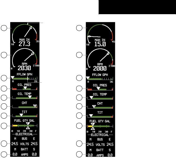
1Engine Manifold Pressure Gauge (MAN IN)
Models 182T, T182T, 206H, T206H – Displays engine power in inches of mercury (in Hg). Turbocharged aircraft have a red portion of the gaugeindicatingthemaximummanifoldpressure range. A white tick mark is displayed indicating the cruise manifold pressure (Model T182T only).
SECTION 3 – ENGINE
INDICATION SYSTEM (EIS)
2Tachometer (RPM) – Shows propeller speeds in revolutions per minute (rpm). Red range indicates propeller overspeed warning; a white high-rpmrangeindicatesabovenormaloperating speeds (Models 172S, 206H, and T206H)
3Fuel Flow Indicator (FFLOW GPH) – Shows the current fuel flow in gallons per hour (gph). For turbocharged aircraft, the indicator displays a small stand-alone green band indicating maximum takeoff fuel flow. A white tick mark indicates the maximum cruise fuel flow (Model T182T only).
4Oil Pressure Indicator (OIL PRES) – Displays pressure of the oil supplied to the engine in pounds per square inch (psi).
5 Oil Temperature Indicator (OIL TEMP)
– Displays the engine oil temperature in degrees Fahrenheit (°F).
6Cylinder Head Temperature Indicator (CHT)
Models 182T, T182T, 206H, T206H – Shows the head temperature of the hottest cylinder (number shown in triangular pointer) in degrees Fahrenheit (°F).
7Exhaust Gas Temperature Indicator (EGT)
Normally-aspirated Aircraft – Displays the exhaust gas temperature of the hottest cylinder (number shown in triangular pointer) in degrees Fahrenheit (°F).
8Turbine Inlet Temperature Indicator (TIT)
Turbocharged Aircraft – Displays the temperature at the turbine inlet in degrees Fahrenheit (°F).
9Vacuum Pressure Indicator (VAC) Models 172R and 172S – Displays vacuum pressure.
190-00384-08 Rev.A |
Garmin G1000 Cockpit Reference Guide for the Cessna Nav III |
3-1 |

SECTION 3 – ENGINE
INDICATION SYSTEM (EIS)
10Fuel Quantity Indicator (FUEL QTY GAL)
– Shows the quantity of fuel in the tanks, in gallons, ranging from zero to full (F) for each fuel tank (left–Landright–R). When full, the indicator displays to 35 gallons per side (26 gallons for the
Models 172R and 172S).
11Engine Hours (Tach) (ENG HRS) Models 172R and 172S – A numeric readout gives the time (in hours) the engine has been in service.
12Voltmeter (M, E BUS VOLTS) – Displays the main and essential bus voltages.
13Ammeter (M, S BATT AMPS) – Shows the main and standby battery load in amperes.
2 |
2 |
3 |
3 |
4 |
4 |
5 |
5 |
7 |
7 |
9 |
9 |
10 |
10 |
11 |
11 |
12 |
12 |
13 |
13 |
1 |
1 |
2 |
2 |
3 |
3 |
4 |
4 |
5 |
5 |
6 |
6 |
7 |
7 |
10 |
10 |
12 |
12 |
13 |
13 |
Model 172R |
Model 172S |
Model 182T |
Model 206H |
|
Figure 3-1 Engine Display (Normally-aspirated Aircraft) |
|
|
3-2 |
Garmin G1000 Cockpit Reference Guide for the Cessna Nav III |
190-00384-08 Rev.A |
|
1
2
3
4
5
6
8
10
12
13
SECTION 3 – ENGINE INDICATION SYSTEM (EIS)
Cruise
Manifold
Pressure
Cruise
Fuel Flow
Model T182T
1
2
|
|
|
|
Maximum |
3 |
|
|
|
Takeoff Fuel |
|
|
|
||
|
|
|
Flow |
|
|
|
|
4
5
6
8
10
12
13
Model T206H
Figure 3-2 Engine Display (Turbocharged Aircraft)
190-00384-08 Rev.A |
Garmin G1000 Cockpit Reference Guide for the Cessna Nav III |
3-3 |