- •Section 1: System Overview
- •1.1 PFD/MFD Controls
- •1.2 PFD Softkeys
- •1.3 MFD Softkeys
- •1.4 MFD Page Groups
- •1.5 Vertical Navigation
- •1.6 Backlighting
- •1.7 XM Radio - Automatic Muting
- •1.8 Database Updates
- •Jeppesen Aviation Database
- •Garmin Databases
- •Section 2: Flight Instruments
- •2.1 Airspeed Indicator
- •Speed Indication
- •Speed Ranges
- •Airspeed Trend Vector
- •Vspeed References
- •2.2 Attitude Indicator
- •2.3 Altimeter
- •Selected Altitude Bug
- •Altitude Trend Vector
- •Barometric Setting Box
- •Altitude Alerting
- •Metric Display
- •Low Altitude Annunciation
- •2.5 Marker Beacon Annunciations
- •2.6 Vertical Speed Indicator
- •2.7 Barometric Altitude Minimums
- •2.8 Horizontal Situation Indicator (HSI)
- •Course Pointer
- •Course Deviation Indicator (CDI)
- •Bearing Pointers and Information Windows
- •DME (optional)
- •Navigation Source
- •2.9 Wind Data
- •2.10 Generic Timer
- •3.1 Engine Display
- •3.2 Lean Display
- •Normally-aspirated Aircraft
- •Turbocharged Aircraft
- •3.3 System Display
- •4.1 Radio Status Indications
- •4.2 Volume
- •4.3 Automatic Squelch
- •4.4 Quickly Activating 121.500 MHz
- •4.5 Optional NAV Radios
- •DME Radio (optional)
- •ADF Radio (optional)
- •Auto-tuning on the PFD
- •Auto-tuning on the MFD
- •4.7 Transponder
- •Mode Selection
- •Reply Status
- •Code Selection
- •Flight ID Reporting
- •5.1 COM Radio Selection
- •5.2 Cabin Speaker
- •5.3 Passenger Address (PA) System (T)182T and (T)206H Only
- •5.4 Marker Beacon Receiver
- •Marker Beacon Signal Sensitivity
- •5.5 Nav Radio Audio Selection
- •5.6 Intercom System (ICS) Isolation
- •5.7 Intercom Squelch Control
- •5.8 Digital Clearance Recorder and Player
- •6.1 AFCS Controls
- •6.2 Flight Director Operation
- •Activating the Flight Director
- •Command Bars
- •AFCS Status Box
- •6.3 Flight Director Modes
- •Pitch Modes
- •Roll Modes
- •6.4 Autopilot Operation
- •Flight Control
- •Engaging the Autopilot
- •Control Wheel Steering
- •Disengaging the Autopilot
- •6.5 Example Procedures
- •Departure
- •Intercepting a VOR Radial
- •Flying a Flight Plan/GPS Course
- •Descent
- •Approach
- •Go Around/Missed Approach
- •6.6 AFCS Annunciations and Alerts
- •AFCS Status Alerts
- •Overspeed Protection
- •Section 7: Navigation
- •7.1 Navigation Map Page
- •Direct-to Navigation from the MFD
- •Direct-to Navigation from the PFD
- •7.3 Navigating an Example Flight Plan
- •7.4 Airport Information
- •7.5 Intersection Information
- •7.6 NDB Information
- •7.7 VOR Information
- •7.8 User Waypoint Information Page
- •7.9 Nearest Airports
- •Nearest Airport Information on the MFD
- •Nearest Airports Information on the PFD
- •7.10 Nearest Intersections
- •7.11 Nearest NDB
- •7.12 Nearest VOR
- •7.13 Nearest User Waypoint
- •7.14 Nearest Frequencies
- •7.15 Nearest Airspaces
- •Section 8: Flight Planning
- •8.1 User Defined Waypoints
- •Select the User WPT Information Page
- •Create User Waypoints from the Navigation Map Page
- •8.2 Viewing the Active Flight Plan
- •8.3 Activate a Stored Flight Plan
- •8.4 Activate a Flight Plan Leg
- •8.5 Stop Navigating a Flight Plan
- •8.6 Invert Active Flight Plan
- •8.7 Create a New Flight Plan
- •Create a New Flight Plan Using the MFD
- •Create a New Flight Plan Using the PFD
- •8.8 Enter an Airway in a Flight Plan
- •8.9 Load a Departure
- •8.10 Load an Arrival
- •8.11 Load an Approach
- •8.13 Store a Flight Plan
- •8.14 Edit a Stored Flight Plan
- •8.15 Delete a Waypoint from the Flight Plan
- •8.16 Invert and Activate a Stored Flight Plan
- •8.17 Copy a Flight Plan
- •8.18 Delete a Flight Plan
- •8.19 Graphical Flight Plan Creation
- •8.20 Trip Planning
- •Section 9: Procedures
- •9.1 Arrivals and Departures
- •Load and Activate a Departure Procedure
- •Load and Activate An Arrival Procedure
- •9.2 Approaches
- •Load and/or Activate an Approach Procedure
- •Activate An Approach in the Active Flight Plan
- •Section 10: Hazard Avoidance
- •10.1 Customizing the Hazard Displays on the Navigation Map
- •10.2 STORMSCOPE® (Optional)
- •Displaying Stormscope Lightning Data on the Navigation Map Page
- •Stormscope Page
- •10.3 XM Weather (Service Optional)
- •Displaying METAR and TAF information on the Airport Information Page
- •Displaying Weather on the Weather Data Link Page
- •Weather Products & Symbols
- •Weather Product Age
- •10.4 Traffic Systems
- •10.5 Terrain and Obstacle Proximity
- •Displaying Terrain and Obstacles on the Terrain Proximity Page
- •Displaying Terrain and Obstacles on the Navigation Map
- •10.6 Terrain Awareness & Warning System (TAWS) Display (Optional)
- •Displaying Terrain on the TAWS Page
- •Enable/Disable Aviation Data
- •TAWS Inhibit
- •Manual System Test
- •Forward Looking Terrain Avoidance (FLTA)
- •Premature Descent Alert (PDA)
- •Excessive Descent Rate Alert (EDR)
- •Displaying Terrain and Obstacles on the Navigation Map
- •Pop-up Alerts
- •TAWS Alerts Summary
- •Alert Annunciations
- •11.1 Reversionary Mode
- •11.2 Abnormal COM Operation
- •11.3 Unusual Attitudes
- •11.4 Stormscope Operation with loss of Heading Input
- •11.5 Hazard Displays with Loss of GPS Position
- •11.6 Dead Reckoning
- •12.1 Alert Level Definitions
- •12.2 NAV III Aircraft Alerts
- •WARNING Alerts
- •CAUTION Alerts
- •12.3 CO Guardian Messages
- •12.4 AFCS Alerts
- •System Status Annunciation
- •12.5 TAWS Alerts
- •12.6 Other G1000 Aural Alerts
- •12.7 G1000 System Annunciations
- •12.8 G1000 System Message Advisories
- •MFD & PFD Message Advisories
- •Database Message Advisories
- •GMA 1347 Message Advisories
- •GIA 63 Message Advisories
- •GIA 63W Message Advisories
- •GEA 71 Message Advisories
- •GTX 33 Message Advisories
- •GRS 77 Message Advisories
- •GMU 44 Message Advisories
- •GDL 69A Message Advisories
- •GDC 74A Message Advisories
- •Miscellaneous Message Advisories
- •Index
SECTION 2
FLIGHT INSTRUMENTS
2.3ALTIMETER
|
|
|
|
Altitude |
Altitude |
|
|
|
Reference |
|
|
|
||
Reference |
|
|
|
Box |
|
||||
Bug |
|
|
|
|
Altitude
Trend Current
Vector Altitude
Barometric
Altitude
Minimums Bug
Barometric
Setting
Box
Figure 2-7 Altimeter
Selected Altitude Bug
The Selected Altitude Bug is displayed at the Selected Altitude or the edge of the tape (whichever is closer to the current altitude) to provide increased altitude awareness and to set the desired hold altitude for the autopilot.
Set the Selected Altitude Bug:
Turn the ALT Knobs to set the SelectedAltitude Bug. The small ALT Knob sets the hundreds and the large ALT Knob sets the thousands. This altitude also appears in the Selected Altitude Box above the Altimeter.
Altitude Trend Vector
The end of the trend vector displays approximately what the altitude will be in six seconds if the current rate of vertical speed is maintained.
Barometric Setting Box
Select barometric pressure:
Turn the BARO Knob to select the desired setting.
Quickly enter standard pressure:
1)Press the PFD Softkey.
2)Press the STD BARO Softkey.
Altitude Alerting
Within 1000 ft |
Within 200 ft |
Deviation of ±200 ft |
Figure 2-8 Altitude Alerting Visual Annunciations
Visual annunciations appear in the Altitude Reference Box. Whenever the setting is changed, the Altitude Alerter is reset. The Altitude Alerter is independent of the Automatic Flight Control System.
2-4 |
Garmin G1000 Cockpit Reference Guide for the Cessna Nav III |
190-00384-08 Rev.A |
Metric Display
Display altitude in meters and barometric pressure in hectopascals:
1)Press the PFD Softkey to display the second level softkeys.
2)Press the ALT UNIT Softkey.
3)Press the METERS Softkey to display altitude in meters.
4)Press the HPA Softkey to display the barometric setting in hectopascals. Press the IN Softkey to display the barometric setting in inches of mercury.
5)Press the BACK Softkey to return to the previous level softkeys.
Figure 2-9 Altimeter (Metric)
SECTION 2
FLIGHT INSTRUMENTS
Low Altitude Annunciation
NOTE: TheLOWALTannunciationisonlyavailable inG1000systemsconfiguredwithWAAS-capable GPS. Also, the LOW ALT annunciation is not available when the G1000 is configured with TAWS (Terrain Awareness & Warning System), unless TAWS is inhibited.
When the Final Approach Fix (FAF) is the active waypointinaGPSWAASapproachusingverticalguidance, a LOW ALT (Low Altitude) annunciation may appear if the current aircraft altitude is at least 164 feet below the prescribed altitude at the FAF. The annunciation initially flashes. After a few seconds the flashing stops and the annunciation is displayed as shown in Figure 2-10.
Low Altitude
Annunciation
Figure 2-10 Low Altitude on GPS Approach
190-00384-08 Rev.A |
Garmin G1000 Cockpit Reference Guide for the Cessna Nav III |
2-5 |
SECTION 2
FLIGHT INSTRUMENTS
2.4VERTICAL DEVIATION/GLIDEPATH/ GLIDESLOPE INDICATOR
The Vertical Deviation and Required Vertical Speed Indicators appear when vertical guidance is being given prior to executing an approach (see Figure 2-11). In systems that are WAAS enabled, the Glidepath Indicator appearsatapointpriortotheFAFwhenexecutinganLPV, LNAV/VNAV, or LNAV+V approach (see Figure 2-12).
Glidepath VNAV Indicator
Target
Altitude
Vertical |
|
|
|
|
Deviation |
|
|
|
Required |
|
||||
Indicator |
|
|
|
Vertical |
|
|
|
||
|
|
|
|
Speed |
Figure 2-11 Vertical Deviation Indications
Figure 2-12 Glidepath Indicator
TheGlideslopeIndicatorappearswhenanILSapproach has been activated and an ILS is tuned in the active NAV receiver field (see Figure 2-13).
Marker Beacon
Annunciation
Glideslope
Indicator
Figure 2-13 Glideslope Indicator
2-6 |
Garmin G1000 Cockpit Reference Guide for the Cessna Nav III |
190-00384-08 Rev.A |
2.5MARKER BEACON ANNUNCIATIONS
Outer Marker |
Middle Marker |
Inner Marker |
SECTION 2
FLIGHT INSTRUMENTS
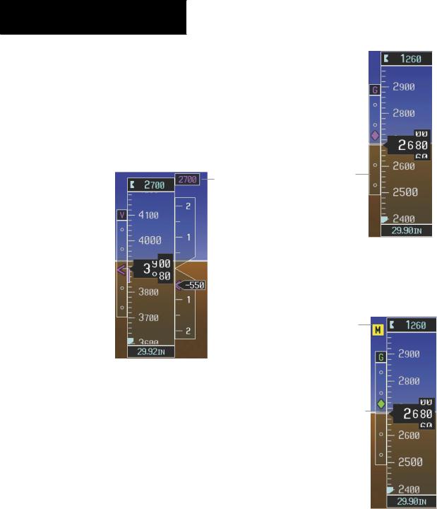
2.7BAROMETRIC ALTITUDE MINIMUMS
Thedesiredbarometricaltitudeminimumscanbesetin the Timer/References Window. The altitude ranges from 0 to 16,000 feet in 10-foot increments. The minimums are reset anytime the power is cycled.
Altimeter
Figure 2-14 Marker Beacon Annunciations
2.6VERTICAL SPEED INDICATOR
Selected Vertical Speed
Vertical Speed Bug
Vertical Speed Pointer
Figure 2-15 Vertical Speed Indicator
The actual vertical speed is displayed inside the pointer.
When the Flight Director is placed in Vertical Speed Mode (by pressing the VS Key) the Vertical Speed Bug is displayed. Press the NOSE UP or NOSE DN Key to adjust.
Figure 2-16 Barometric Minimum Descent Altitude Settings
The desired barometric minimum descent altitude (MDA, or Decision Height, DH) can be set in the Timer/ References Window.
Visual annunciations alert the pilot when approaching the MDA:
•When the aircraft altitude descends to within 2500 feet of the MDA setting, the Barometric Minimum Box appears with the altitude in light blue text. The bug appears on the tape in light blue once in range.
•When the aircraft passes through 100 feet of the MDA, the bug and text turn white.
•Once the aircraft descends past the MDA, the bug andtextturnyellowandtheauralalert,“Minimums Minimums”, is generated.
Alerting is inhibited while the aircraft is on the ground. IftheaircraftclimbsafterhavingreachedtheMDA,onceit reaches 50 feet above the MDA, alerting is disabled.
190-00384-08 Rev.A |
Garmin G1000 Cockpit Reference Guide for the Cessna Nav III |
2-7 |