- •Section 1: System Overview
- •1.1 PFD/MFD Controls
- •1.2 PFD Softkeys
- •1.3 MFD Softkeys
- •1.4 MFD Page Groups
- •1.5 Vertical Navigation
- •1.6 Backlighting
- •1.7 XM Radio - Automatic Muting
- •1.8 Database Updates
- •Jeppesen Aviation Database
- •Garmin Databases
- •Section 2: Flight Instruments
- •2.1 Airspeed Indicator
- •Speed Indication
- •Speed Ranges
- •Airspeed Trend Vector
- •Vspeed References
- •2.2 Attitude Indicator
- •2.3 Altimeter
- •Selected Altitude Bug
- •Altitude Trend Vector
- •Barometric Setting Box
- •Altitude Alerting
- •Metric Display
- •Low Altitude Annunciation
- •2.5 Marker Beacon Annunciations
- •2.6 Vertical Speed Indicator
- •2.7 Barometric Altitude Minimums
- •2.8 Horizontal Situation Indicator (HSI)
- •Course Pointer
- •Course Deviation Indicator (CDI)
- •Bearing Pointers and Information Windows
- •DME (optional)
- •Navigation Source
- •2.9 Wind Data
- •2.10 Generic Timer
- •3.1 Engine Display
- •3.2 Lean Display
- •Normally-aspirated Aircraft
- •Turbocharged Aircraft
- •3.3 System Display
- •4.1 Radio Status Indications
- •4.2 Volume
- •4.3 Automatic Squelch
- •4.4 Quickly Activating 121.500 MHz
- •4.5 Optional NAV Radios
- •DME Radio (optional)
- •ADF Radio (optional)
- •Auto-tuning on the PFD
- •Auto-tuning on the MFD
- •4.7 Transponder
- •Mode Selection
- •Reply Status
- •Code Selection
- •Flight ID Reporting
- •5.1 COM Radio Selection
- •5.2 Cabin Speaker
- •5.3 Passenger Address (PA) System (T)182T and (T)206H Only
- •5.4 Marker Beacon Receiver
- •Marker Beacon Signal Sensitivity
- •5.5 Nav Radio Audio Selection
- •5.6 Intercom System (ICS) Isolation
- •5.7 Intercom Squelch Control
- •5.8 Digital Clearance Recorder and Player
- •6.1 AFCS Controls
- •6.2 Flight Director Operation
- •Activating the Flight Director
- •Command Bars
- •AFCS Status Box
- •6.3 Flight Director Modes
- •Pitch Modes
- •Roll Modes
- •6.4 Autopilot Operation
- •Flight Control
- •Engaging the Autopilot
- •Control Wheel Steering
- •Disengaging the Autopilot
- •6.5 Example Procedures
- •Departure
- •Intercepting a VOR Radial
- •Flying a Flight Plan/GPS Course
- •Descent
- •Approach
- •Go Around/Missed Approach
- •6.6 AFCS Annunciations and Alerts
- •AFCS Status Alerts
- •Overspeed Protection
- •Section 7: Navigation
- •7.1 Navigation Map Page
- •Direct-to Navigation from the MFD
- •Direct-to Navigation from the PFD
- •7.3 Navigating an Example Flight Plan
- •7.4 Airport Information
- •7.5 Intersection Information
- •7.6 NDB Information
- •7.7 VOR Information
- •7.8 User Waypoint Information Page
- •7.9 Nearest Airports
- •Nearest Airport Information on the MFD
- •Nearest Airports Information on the PFD
- •7.10 Nearest Intersections
- •7.11 Nearest NDB
- •7.12 Nearest VOR
- •7.13 Nearest User Waypoint
- •7.14 Nearest Frequencies
- •7.15 Nearest Airspaces
- •Section 8: Flight Planning
- •8.1 User Defined Waypoints
- •Select the User WPT Information Page
- •Create User Waypoints from the Navigation Map Page
- •8.2 Viewing the Active Flight Plan
- •8.3 Activate a Stored Flight Plan
- •8.4 Activate a Flight Plan Leg
- •8.5 Stop Navigating a Flight Plan
- •8.6 Invert Active Flight Plan
- •8.7 Create a New Flight Plan
- •Create a New Flight Plan Using the MFD
- •Create a New Flight Plan Using the PFD
- •8.8 Enter an Airway in a Flight Plan
- •8.9 Load a Departure
- •8.10 Load an Arrival
- •8.11 Load an Approach
- •8.13 Store a Flight Plan
- •8.14 Edit a Stored Flight Plan
- •8.15 Delete a Waypoint from the Flight Plan
- •8.16 Invert and Activate a Stored Flight Plan
- •8.17 Copy a Flight Plan
- •8.18 Delete a Flight Plan
- •8.19 Graphical Flight Plan Creation
- •8.20 Trip Planning
- •Section 9: Procedures
- •9.1 Arrivals and Departures
- •Load and Activate a Departure Procedure
- •Load and Activate An Arrival Procedure
- •9.2 Approaches
- •Load and/or Activate an Approach Procedure
- •Activate An Approach in the Active Flight Plan
- •Section 10: Hazard Avoidance
- •10.1 Customizing the Hazard Displays on the Navigation Map
- •10.2 STORMSCOPE® (Optional)
- •Displaying Stormscope Lightning Data on the Navigation Map Page
- •Stormscope Page
- •10.3 XM Weather (Service Optional)
- •Displaying METAR and TAF information on the Airport Information Page
- •Displaying Weather on the Weather Data Link Page
- •Weather Products & Symbols
- •Weather Product Age
- •10.4 Traffic Systems
- •10.5 Terrain and Obstacle Proximity
- •Displaying Terrain and Obstacles on the Terrain Proximity Page
- •Displaying Terrain and Obstacles on the Navigation Map
- •10.6 Terrain Awareness & Warning System (TAWS) Display (Optional)
- •Displaying Terrain on the TAWS Page
- •Enable/Disable Aviation Data
- •TAWS Inhibit
- •Manual System Test
- •Forward Looking Terrain Avoidance (FLTA)
- •Premature Descent Alert (PDA)
- •Excessive Descent Rate Alert (EDR)
- •Displaying Terrain and Obstacles on the Navigation Map
- •Pop-up Alerts
- •TAWS Alerts Summary
- •Alert Annunciations
- •11.1 Reversionary Mode
- •11.2 Abnormal COM Operation
- •11.3 Unusual Attitudes
- •11.4 Stormscope Operation with loss of Heading Input
- •11.5 Hazard Displays with Loss of GPS Position
- •11.6 Dead Reckoning
- •12.1 Alert Level Definitions
- •12.2 NAV III Aircraft Alerts
- •WARNING Alerts
- •CAUTION Alerts
- •12.3 CO Guardian Messages
- •12.4 AFCS Alerts
- •System Status Annunciation
- •12.5 TAWS Alerts
- •12.6 Other G1000 Aural Alerts
- •12.7 G1000 System Annunciations
- •12.8 G1000 System Message Advisories
- •MFD & PFD Message Advisories
- •Database Message Advisories
- •GMA 1347 Message Advisories
- •GIA 63 Message Advisories
- •GIA 63W Message Advisories
- •GEA 71 Message Advisories
- •GTX 33 Message Advisories
- •GRS 77 Message Advisories
- •GMU 44 Message Advisories
- •GDL 69A Message Advisories
- •GDC 74A Message Advisories
- •Miscellaneous Message Advisories
- •Index
2.1AIRSPEED INDICATOR
Vspeed
References
Actual Airspeed
Speed Ranges
Airspeed Trend
True Airspeed Vector
Box
Figure 2-4 Airspeed Indicator
Speed Indication
The indicated airspeed is displayed inside the black pointer. The pointer becomes red upon reaching Vne.
Figure 2-5 Red Pointer at Vne
Speed Ranges
The color coded speed range strip denotes flaps operating range, normal operating range, and never exceed speed (Vne). A red range is also present for low speed awareness. Refer to the Pilot’s Operating Handbook (POH) for airspeed limitations and indicator markings.
Airspeed Trend Vector
The end of the trend vector displays approximately what the airspeed will be in 6 seconds if the current rate of acceleration/deceleration is maintained.
SECTION 2
FLIGHT INSTRUMENTS
Vspeed References
Vspeed References are turned on or off in the Timer/References Window. Press the TMR/REF Softkey to display the widow. When active (ON), the Vspeeds are displayed at their respective locations to the right of the airspeed scale. To activate the Vspeed References, display the Timer/Reference Window and turn the large FMS Knob to place the cursor in the ON/OFF field. Turn the small FMS Knob to select ON or OFF.
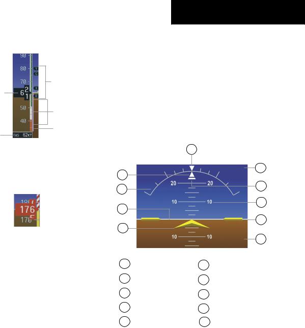
2.2ATTITUDE INDICATOR
|
10 |
|
|
1 |
|
|
9 |
|
|
|
|
2 |
|
|
8 |
|
|
|
|
3 |
|
|
7 |
|
|
|
|
|
|
|
6 |
4 |
|
|
|
|
|
|
5 |
1 |
Roll Pointer |
6 |
Aircraft Wing Tips |
2 |
Roll Scale |
7 |
Pitch Scale |
3 |
Horizon Line |
8 |
Slip/Skid Indicator |
4 |
Aircraft Symbol |
9 |
Sky Representation |
5 |
Land Representation |
10 |
Roll Index Zero |
Figure 2-6 Attitude Indicator
TheSlip/SkidIndicatorislocatedundertherollpointer and moves laterally away from the pointer to indicate lateral acceleration. One Slip/Skid indicator displacement is equal to one ball displacement when compared to a traditional slip/skid indicator.
190-00384-08 Rev.A |
Garmin G1000 Cockpit Reference Guide for the Cessna Nav III |
2-3 |