

AIRWAYS – Pressing this softkey displays/removes airways information. The default is dependent on map setup option selected. Pressing cycles through all airways displayed (AIRWY ON), low altitude airwaysonly(AIRWYLO),andhighaltitudeairways only (AIRWY HI).
STRMSCP (optional) – Pressing this softkey displays/ removesStormscopelightningdataontheNavigation Map.
NEXRAD (optional) – Pressing this softkey displays/ removes precipitation data on the Navigation Map.
XM LTNG (optional) – Pressing this softkey displays/ removes XM Radio lightning data on the Navigation Map.
BACK–PressingthissoftkeydisplaystheENGINEand MAP top level softkeys.
DCLTR (declutter) – Pressing this softkey removes map information in three levels.
SHWCHRT(ShowChart)(optional)–Pressingthissoftkey displays optional FliteCharts or ChartView charts.
CHKLIST (checklist)(optional) – Pressing the CHKLIST Softkey displays the Checklist Page.
ENGINE – Displays engine softkeys.
DONE–Pressingthissoftkeychecksoffachecklistitem. If an item is already checked, an UNDO Softkey is displayed.
EXIT – Press to exit the checklist.
EMERGCY – Pressing this softkey displays the emergency checklist.
Nearest Group
Auxiliary Page Group
Waypoint Page Group
Map Page Group
SECTION 1
SYSTEM OVERVIEW
1.4MFD PAGE GROUPS
1)Turn the large FMS Knob until the desired page group is selected.
2)Turn the small FMS Knob to select pages within the group. See Figure 1-7.
Number of Pages in Current
Group
|
Figure 1-7 Page Group Icon |
Selected Page |
|
190-00384-08 Rev.A |
Garmin G1000 Cockpit Reference Guide for the Cessna Nav III |
1-9 |
|

SECTION 1
SYSTEM OVERVIEW
1.5VERTICAL NAVIGATION
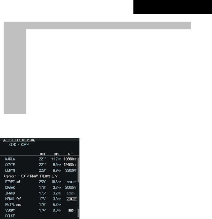
OneoftwoaltitudesourcesisusedbytheG1000when giving vertical navigation guidance. WAAS GPS altitude is used when giving guidance for a WAAS approach after the Final Approach Fix. Baro corrected altitude is used when vertical guidance is given in all other situations and in non-WAAS systems.
The G1000 system can use altitude constraints associated with lateral waypoints to give guidance for vertical navigation. These altitudes are, depending on the specificinstance,enteredbythepilotorretrievedfromthe published altitudes in the navigation database.
The navigation database only contains altitudes for procedures that call for “Cross at” altitudes. If the procedure states “Expect to cross at,” then the altitude is not in the database. In this case the altitude may be entered manually.
NOTE: All arrival procedure altitudes contained in thenavigationdatabaseareforturbojetaircraftonly. Alterorenteraltitudesasdesiredtocomplywiththe ATC clearance.
When activating or loading an arrival or approach procedure into an active flight plan, the VNV ‘ALT’ fields are populated with any altitudes that can be retrieved from the navigation database.
Since altitudes loaded with an arrival procedure are published only for turbojet aircraft, the altitudes are displayed as white text indicating that the altitudes are displayed for reference only. An arrival waypoint altitude may be used (or “designated”) as is, or changed to a different altitude. An altitude is designated by pressing the FMS Knob and turning the large FMS Knob to place the cursor on the desired altitude and pressing the ENTKey or entering a different value and pressing the ENT Key. The altitude is now displayed as light blue text, indicating that
the altitude is now designated to give vertical speed and deviation guidance.
Approachwaypointaltitudeconstraintsareautomatically designated when the approach is loaded. These altitudes are also displayed as light blue text. Waypoint altitude constraints designated up to, but not including the FAF. The FAF is always a “reference only” altitude and cannot be designated, unless the selected approach does not provide vertical guidance. In this case, the FAF altitude can be designated manually.
Altitudes that have been designated for use in vertical guidancemayalsobemade“non-designated”byplacingthe cursor over the desired altitude and pressing the CLR Key. Otherdisplayedaltitudesmaychangeduetore-calculations or rendered invalid as a result of manually changing an altitude to a non-designated altitude.
To help interpret the meanings of how the altitudes are presented, keep the following points in mind:
•When the altitude is displayed in light blue, the system is using that altitude (designated) to determine vertical speed and deviation guidance.
•Whenthealtitudeisdisplayedinwhite,itisnotbeing used by the system (non-designated) to determine the vertical speed and deviation guidance.
•Analtitudedisplayedassmalltextisanaltitudethat is published in the navigation database.
•Altitudes displayed as a light blue subdued text cannot be used in the current vertical navigation calculations.
1-10 |
Garmin G1000 Cockpit Reference Guide for the Cessna Nav III |
190-00384-08 Rev.A |
|
|
|
|
SECTION 1 |
|
|
|
|
|
SYSTEM OVERVIEW |
|
|
|
|
|
|
|
|
|
|
|
|
|
|
White Text |
Light Blue Text |
|
Light Blue Subdued Text |
|
|
|
|
|
|
|
Large Text |
Altitude calculated by the system |
Altitude has been entered by the |
|
The system cannot use this altitude |
|
|
estimating the altitude of the |
pilot. Altitude is designated for |
|
in determining vertical speed and |
|
|
aircraft as it passes over the |
use in giving vertical speed and |
|
deviation guidance. |
|
|
navigation point. This altitude |
deviation guidance. Altitude does |
|
|
|
|
is provided as a reference and |
not match the published altitude |
|
|
|
|
is not designated to be used in |
in navigation database or no |
|
|
|
|
determining vertical speed and |
published altitude exists. |
|
|
|
|
deviation guidance. |
|
|
|
|
|
|
|
|
|
|
Small Text |
Altitude is not designated to |
Altitude is designated for use in |
|
The system cannot use this altitude |
|
|
be used in determining vertical |
giving vertical speed and deviation |
|
in determining vertical speed and |
|
|
speed and deviation guidance. |
guidance. Altitude has been |
|
deviation guidance. |
|
|
Altitude has been retrieved from |
retrieved from the navigation |
|
|
|
|
the navigation database and is |
database or has been entered by |
|
|
|
|
provided as a reference. |
the pilot and matches a published |
|
|
|
|
|
altitude in the navigation database. |
|
|
|
|
|
|
|
|
|
Table 1-1 VNV Altitude Text Size and Color
Refer to Figure 1-8 and Table 1-1 for more detail regarding the significance of text size and color.
|
|
|
Large White |
||
|
|
|
|||
|
|
|
|
|
Text |
|
|
|
|
Large Light |
|
|
|
|
|
||
|
|
|
|
|
Blue Text |
|
|
|
|
|
Small Light |
|
|
|
|
|
|
|
|
|
|
|
Blue Text |
|
|
|
|
|
Small Light |
|
|
|
|
|
|
|
|
Blue Subdued |
|||
|
|
|
|
|
Text |
|
|
|
|
Small White |
|
|
|
|
|
|
Text with |
|
|
|
|
|
|
|
|
|
|
|
Altitude |
|
|
|
|
|
Restriction |
Figure 1-8 VNAV Altitudes |
|
|
|
Bar |
|
Some altitudes retrieved from the database have associated restrictions indicating to stay ‘At’, ‘At or Above’, or ‘At or Below’ a specific altitude. These restrictions are indicated using a ‘bar’ above and/or below the appropriate altitude as shown in Figure 1-9.
 Cross AT or ABOVE 5,000 ft
 Cross AT 2,300 ft
 Cross AT or BELOW 3,000 ft
Figure 1-9 Altitude Restrictions
See Section 7 - Navigation, for a sample flight plan which further illustrates vertical navigation in more detail.
190-00384-08 Rev.A |
Garmin G1000 Cockpit Reference Guide for the Cessna Nav III |
1-11 |