

α Series Simple Application Controllers |
What You Should Know Before Starting to Program 4 |
|
4.What You Should Know Before Starting to Program
This section describes the basic functions and background information necessary to operate the AL-PCS/WIN-E. Please read and understand this section prior to beginning your first program.
There are two screens that can be accessed from the AL-PCS/WIN-E, the Function Block Diagram base (FBD window) and the System Sketch Monitoring screen.
4.1Screen Identification
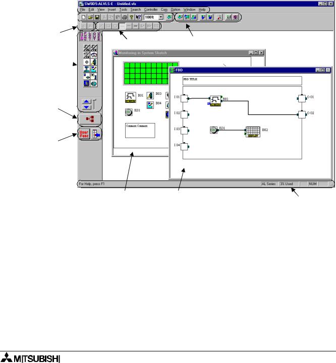
The Toolbars have been labeled on the screen below for the user’s reference. These Toolbars can be turned On or Off in the View menu. The Menu Bar runs across the top of the screen. The two main viewing screens will be discussed later in the chapter.
Menu bar


Standard 
 toolbar

Image toolbar |
Drawing toolbar |
Controller toolbar |
|
||
|
|
Accessories toolbar 
Wiring toolbar
User Function toolbar
System Sketch Monitor window |
Function Block Diagram (FBD) window |
Status bar |
Menu bar - The “File”, “Edit”, View”, Insert”, Tools”, Search”, Controller”, Com”, “Option”, “Window”, and “Help” options are located in the menu bar. Further information can be found in the chapter 5 and Help on AL-PCS/WIN-E.
Standard toolbar - The Standard toolbar contains the “New”, “Open”, “Save”, “Cut”, “Paste”, “Print”, “About”, “Help”, “Zoom”, and “Read from Controller” buttons. Further information can be found in the Help on AL-PCS/WIN-E.
Image toolbar - The Image toolbar contains the “Import” and “Export” buttons within the Monitoring in System Sketch Window. The import button is used for inserting the previously exported image (*.img) file into the Monitoring in System Sketch Window. Further information can be found in Help on AL-PCS/WIN-E.
Drawing toolbar - The Drawing toolbar contains the “Line”, “Rectangle”, “Oval”, “Thin”, “Medium”, “Thick”, “Line Color”, Brush Color”, and “Align Drawing Objects” buttons. Further information can be found in the Help on AL-PCS/WIN-E.
4-1

α Series Simple Application Controllers |
What You Should Know Before Starting to Program 4 |
|
|
Controller toolbar - The Controller toolbar contains the “Write to Controller”, “Verify Controller Data”, “Diagnosis of controller”, “Run Controller”, “Stop Controller”, “Auto FBD Wizard”, “Start/ Stop Monitor”, and “Start / Stop Simulation” buttons. Further information can be found in chapter 8 ~ 10 and Help on AL-PCS/WIN-E.
Accessories toolbar - The Accessories toolbar contains the “Input Signals”, “Functions”, “Logic Functions”, “Output Signals”, and “User Functions” Accessory toolbar. Further information can be found in the Help on AL-PCS/WIN-E.
Table 4.1: Accessories toolbar
|
|
|
|
|
Toolbar |
Description |
|
|
|
|
|
|
Input Signals |
Input signals accessory toolbar are icons for the input signal and system bit. |
|
|
|
|
|
|
Functions |
Functions accessory toolbar are icons for the function blocks. |
|
|
|
|
|
|
Logic Functions |
Logic functions accessory toolbar are icons for the logic function blocks. |
|
|
|
|
|
|
Output Signals |
Output signals accessory toolbar are icons for the Output signal and control bit. |
|
|
|
|
|
|
User Functions |
User functions accessory toolbar are icons for the registered user function. |
|
|
|
|
|
|
|
|
|
Wiring toolbar - The Wiring toolbar is only the “wiring” button. Further information can be found in chapter 6 and Help on AL-PCS/WIN-E.
User function toolbar - The User function toolbar are “User Func” and “User Func Registration” buttons. Further information can be found in the chapter 6 and the Help on AL- PCS/WIN-E.
Status bar - The Status bar is current status of the “used series”, “percentage of the used function block”, “caps lock key”, “num lock key”, and “scroll lock key”. Further information can be found in Help on AL-PCS/WIN-E.
4-2
α Series Simple Application Controllers |
What You Should Know Before Starting to Program 4 |
|
|
4.2The Function Block Diagram (FBD) Window
The Function Block Diagram (FBD) window is used to program the α series controller. The FBD window consists of a large wiring area (lime green by default), a title box and input and output rectangles vertically along the right and left hand sides, respectively. Programming components are placed on the wiring area or in the rectangles, and connected by single wires to construct the program for the α series. The FBD window is also known as FBD Wiring area.
Title bar
Output
Input
Edit program area
The user can perform the following ten operations using FBD window. Refer to Chapter 6 for more details. The size for edit program area can be changed by the operation of mouse.
1)Place the I/O signals and functions using the Accessories Toolbar.
2)Assign parameters to functions.
3)Wire the various program components together (with the help of Wiring Analyser).
4)Writes the Program logic and I/O device’s information to the α series.
5)Invoke Auto FBD Wizard to begin to program with guidance.
6)Test the program logic with Internal Devices (Input and Output signals placed in the FBD wiring area).
7)Simulate and check the programming logic off-line without connecting an α series. The user can:
-force input signals ON/OFF
-change function parameters (timers, counters, analog data, etc.)
-display comments or function values on screen
-Monitor component status via changing wire colors (ex. Red Wire = OFF, Blue Wire = ON)
8)Read information from an α series and recreate the Program on the FBD window.
9)Monitor an α series on-line.
10)Print the FBD screen and component information shown on the FBD window.
4-3
α Series Simple Application Controllers |
What You Should Know Before Starting to Program 4 |
|
|
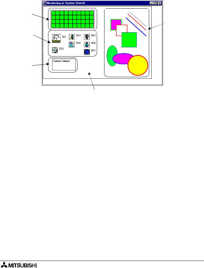
4.3The Monitoring in System Sketch Window
The Monitoring in System Sketch window is the customizing monitor window. The icons for I/O, the function blocks, the images, and the state of LCD, etc. can be displayed in this window. Further information can be found in chapter 7.
LCD image object
Draw object
Function blocks, operation switches input and output object
Comment object
Edit system sketch area
The following operations can be performed in System Sketch window. The size for the edit system sketch area can be changed by the operation of mouse.
1)Draw a diagram using the Drawing toolbar.
2)Place the I/O devices and Function Blocks to represent the α series set-up.
3)Place OLE components in the System Sketch window.
4)Monitor/test an operational α series.
5)Simulate and check the programming logic without connecting the actual α series.
6)Print the System Sketch Monitor window and the component information contained in the window.
7)Import Bitmap Images.
4-4