

α Series Simple Application Controllers |
Function Block Diagram (FBD) Programming 6 |
|
|
6.5Setup Icons
The dialog box of all icons contains the comment box, the Display comment check box and the Display Signal Number box. This dialog box can be viewed by double clicking on the icon. The Display Comment box will display the comment only when checked.
Similarly, the Display Signal Number box will display the signal number next to the icon if checked.
Double click on icon to open parameter window.
Double click on icon to open parameter window.
6.5.1Comments
The Comment Edit box is used to enter a comment which will be displayed on the top of the icon. This can be up to 256 characters but only 16 characters will be considered for display. However, when printing icon information, the comment over 16 characters will be printed, too.
6.5.2Parameter of Function Blocks
Function block parameters can be viewed by double clicking on the Function Block. A dialog box will pop up that shows the parameters that can be adjusted and a comments section for producing easy documentation. Each Function Block has its own set of Parameters that may be set including the various Display Boxes shown at the right.
Further information about parameter of each function block can be found in the programming manual and “Help” on the AL-PCS/WIN-E.
Note:
If using the slider portion of the parameter settings, the value can only be set from 0 - 100. If entering the digits in the box, the listed maximum tolerances can be entered.
6-17
α Series Simple Application Controllers |
Function Block Diagram (FBD) Programming 6 |
|
|
6.6Auto FBD Wizard (Only AL-**M*-*)
The program can be easily created using the Auto FBD Wizard according to the procedure of 8 clear steps. The user can proceed forwards and backwards along this line. Each step is accompanied by a guidance box that will bring up instructions in a dialog box. In the procedure of eight steps, the following 6 content is set.
However, this command supports only the α series (Model: AL-**M*-*). When choosing α2 series, this command does not support the Auto FBD Wizard.
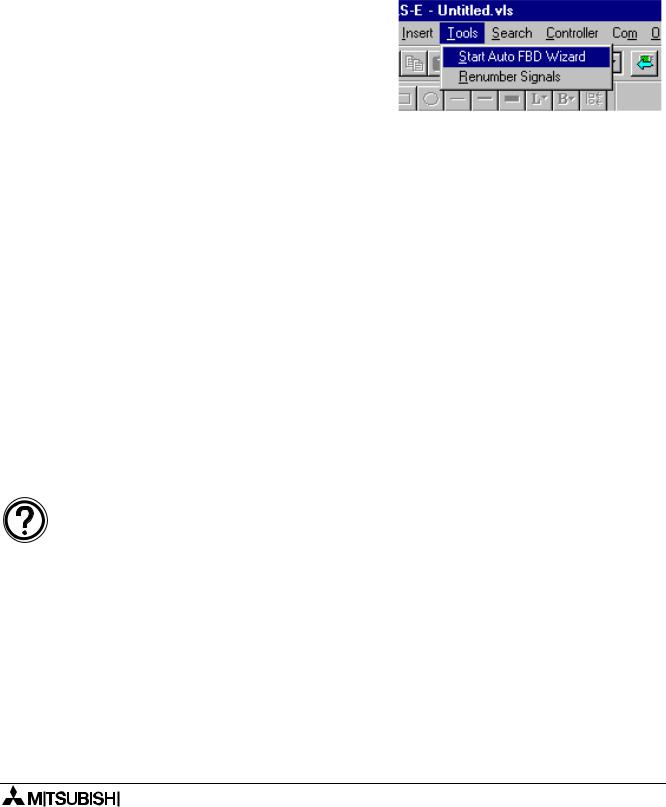
Open the Auto FBD Wizard with the icon or the Start FBD Auto Wizard option from the Tools Menu.
1)Choose an output (Step 1)
2)Select up to 4 function blocks in the following lists to be used (Step 2, 3). Use the boolean automatically if necessary.
-Set/Reset function block
-Delay function block
-Alternate function block
-Flicker function block
-One Shot function block
-Counter function block
-Compare function block
3)The combination of the function blocks to be used is selected (Step 4).
4)Choose the Input Signal for bit Input Pin of the left most function block (Step 5, 6) Select up to 4 signals for one Input Pin.
5)Set the parameters for the function block(s) and select the signal for the Clear Pin and Word Input Pin (Step 7)
6)Check operation (Step 8)
Note:
•Display the Help file concerning the Auto FBD wizard when Clicking the “Guidance” check box.
•To move back to previous menus, click “Back” button.
•To go to next menu, click “Next” button.
If the setting or selection do not finish in the menu (step), “NEXT” is disabled.
6-18

α Series Simple Application Controllers |
Function Block Diagram (FBD) Programming 6 |
|
|
6.6.1Choose an Output (Step 1)
Select one target output for the program to be created from Auto FBD Wizard. Click a target output terminal to select.
Click the “NEXT” button to proceed to the next step when selecting it.
When the icon has already been put on the output terminal with the FBD base, the icon will be display ed in the output terminal.
To allocate the icon:
Click the icon from the output icon in the left of the screen list, and click the output terminal which needs to be allocated again.
To delete the icon to be allocated:
Move the output icon to be deleted from the output terminal to the trash bin by drag & drop.
6-19
α Series Simple Application Controllers |
Function Block Diagram (FBD) Programming 6 |
|
|
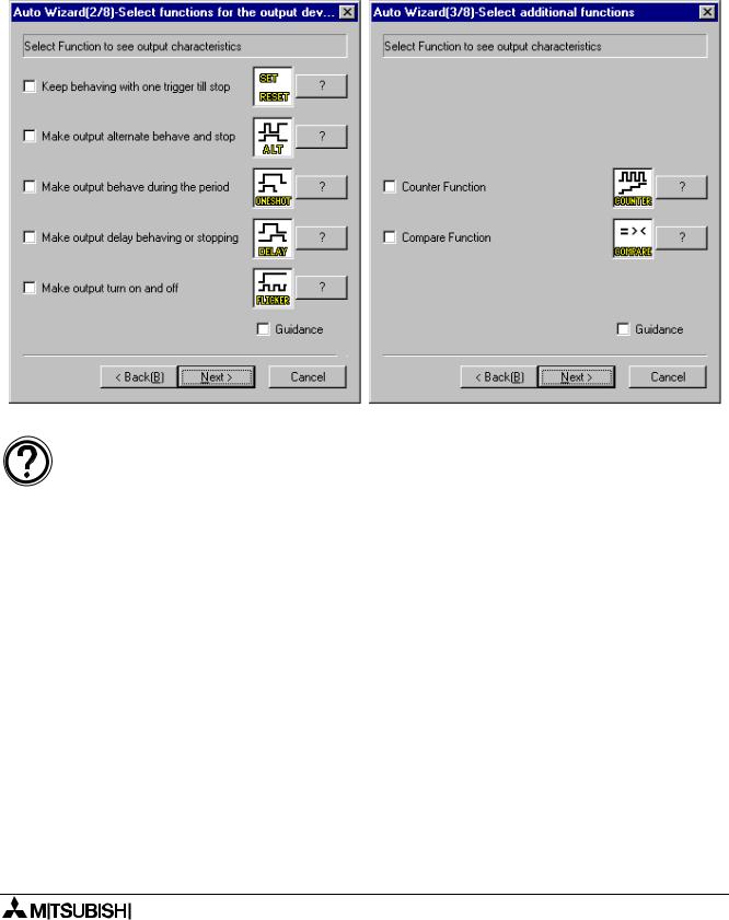
6.6.2Choose Function Blocks (Step 2, 3)
A list of function blocks appears on the screen from which up to 4 total blocks can be chosen to place in the circuit with the output from the following dialog boxes. Click the check box in the function block to be used. The Blocks that can be selected are the Set/Reset, Alternate (ALT), One Shot, Delay, Flicker, Counter and the Compare functions.
Click “NEXT” button to proceed.
Note:
Choose the box with the “?” mark to find out more information on a particular function.
6-20