

SOFTWARE MANUAL
α SIMPLE APPLICATION CONTROLLER

α Seires Simple Application Controllers
Foreword
•This manual contains text, diagrams and explanations which will guide the reader in the correct programming and operation of the α/α2 series controller.
•Before attempting to install or use the α/α2 Series Controller this manual should be read and understood.
•If in doubt at any stage of the installation of the α/α2 Series Controller always consult a professional electrical engineer who is qualified and trained to local and national standards which apply to the installation site.
•If in doubt about the operation or use of the α/α2 Series Controller please consult the nearest Mitsubishi Electric distributor.
•Under no circumstances will Mitsubishi Electric be liable or responsible for any consequential damage that may arise as a result of the installation or use of this equipment.
•All examples and diagrams shown in this manual are intended only as an aid to understanding the text, not to guarantee operation. Mitsubishi Electric will accept no responsibility for actual use of the product based on these illustrative examples.
•Please contact a Mitsubishi Electric distributor for more information concerning applications in life critical situations or high reliability.
•This manual is subject to change without notice.
This manual confers no industrial property rights or any rights of any other kind, nor does it confer any patent licenses. Mitsubishi Electric Corporation cannot be held responsible for any problems involving industrial property rights which may occur as a result of using the contents noted in this manual.
© 2005 MITSUBISHI ELECTRIC CORPORATION

α Series Simple Application Controllers
AL-PCS/WIN-E
Software Manual
Manual number : JY992D74001
Manual revision : J
Date |
: August 2005 |
i

α Series Simple Application Controllers
ii

α Series Simple Application Controllers
FAX BACK
Mitsubishi has a world wide reputation for its efforts in continually developing and pushing back the frontiers of industrial automation. What is sometimes overlooked by the user is the care and attention to detail that is taken with the documentation. However, to continue this process of improvement, the comments of the Mitsubishi users are always welcomed. This page has been designed for you, the reader, to fill in your comments and fax them back to us. We look forward to hearing from you.
Fax numbers: |
|
|
Your name.................................................... |
Mitsubishi Electric |
.... |
|
..................................................................... |
America |
(01) |
847-478-2253 |
Your company .............................................. |
Australia |
(02) |
638-7072 |
..................................................................... |
Germany |
(0 21 02) 4 86-1 12 |
Your location: ............................................... |
|
Spain |
(34) |
93 589-1579 |
..................................................................... |
United Kingdom |
(01707) 278-695 |
|
|
Please tick the box of your choice |
|
|
|
What condition did the manual arrive in? |
Good |
Minor damage |
Unusable |
Will you be using a folder to store the manual? Yes |
No |
|
|
What do you think to the manual presentation? Tidy |
Unfriendly |
|
|
Are the explanations understandable? |
Yes |
Not too bad |
Unusable |
Which explanation was most difficult to understand: ..................................................................
....................................................................................................................................................
Are there any diagrams which are not clear? |
Yes |
No |
|
If so,which:.................................................................................................................................. |
|
|
|
What do you think to the manual layout? |
Good |
Not too bad |
Unhelpful |
If there one thing you would like to see improved, what is it?.....................................................
....................................................................................................................................................
....................................................................................................................................................
Could you find the information you required easily using the index and/or the contents, if
possible please identify your experience: ...................................................................................
....................................................................................................................................................
....................................................................................................................................................
....................................................................................................................................................
....................................................................................................................................................
Do you have any comments in general about the Mitsubishi manuals? .....................................
....................................................................................................................................................
....................................................................................................................................................
....................................................................................................................................................
....................................................................................................................................................
Thank you for taking the time to fill out this questionnaire. We hope you found both the product and this manual easy to use.
iii

α Series Simple Application Controllers
iv
α Series Simple Application Controllers
Guidelines for the safety of the user and protection of AL-PCS/WIN-E
This manual provides information for the use of AL-PCS/WIN-E. The manual has been written to be used by trained and competent personnel. The definition of such a person or persons is as follows;
a)Any engineer who is responsible for the planning, design and construction of automatic equipment using the product associated with this manual should be of a competent nature, trained and qualified to the local and national standards required to fulfill that role. These engineers should be fully aware of all aspects of safety with regards to automated equipment.
b)Any commissioning or service engineer must be of a competent nature, trained and qualified to local and national standards required to fulfill that job. These engineers should also be trained in the use and maintenance of the completed product. This includes being completely familiar with all associated documentation for the said product. All maintenance should be carried out in accordance with established safety practices.
c)All operators of the completed equipment (see Note) should be trained to use that product in a safe manner in compliance to established safety practices. The operators should also be familiar with documentation which is connected with the actual operation of the completed equipment.
Note : the term ‘completed equipment’ refers to a third party constructed device which contains or uses the product associated with this manual.
Notes on the symbology used in this manual
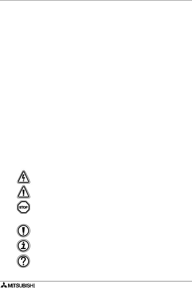
At various times through out this manual certain symbols will be used to highlight points of information which are intended to ensure the users personal safety and protect the integrity of equipment. Whenever any of the following symbols are encountered its associated note must be read and understood. Each of the symbols used will now be listed with a brief description of its meaning.
Hardware warnings
1)Indicates that the identified danger WILL cause physical and property damage.
2)Indicates that the identified danger could POSSIBLY cause physical and property damage.
3)Indicates a point of further interest or further explanation.
Software warning
4) Indicates special care must be taken when using this element of software.
5) Indicates a special point of which the user of the associated software element should be aware.
6) Indicates a point of interest or further explanation.
v

αSeries Simple Application Controllers
•Under no circumstances will Mitsubishi Electric be liable or responsible for any consequential damage that may arise as a result of the installation or use of this equipment.
•All examples and diagrams shown in this manual are intended only as an aid to understanding the text, not to guarantee operation. Mitsubishi Electric will accept no responsibility for actual use of the product based on these illustrative examples.
•Please contact a Mitsubishi distributor for more information concerning applications in life critical situations or high reliability.
vi

α Series Simple Application Controllers
Further Information Manual Lists
|
|
|
|
|
|
|
|
Manual Name |
Manual No. |
Description |
|
|
|
|
|
|
|
|
|
α Software Manual |
JY992D74001 |
This manual contains explanations of operation |
|
|
|
<This manual> |
|
for AL-PCS/WIN-E Programming Software. |
|
|
|
|
|
|
|
|
|
|
|
This manual contains hardware explanations for |
|
|
|
α Hardware Manual |
JY992D74201 |
wiring, installation and specification for α series |
|
|
|
|
|
controllers. |
|
|
|
|
|
|
|
|
|
α Programming Manual |
JY992D76601 |
This manual contains instruction explanations for |
|
|
the α Series controllers. |
|
|||
|
|
<English only> |
|
|
|
|
|
|
|
|
|
|
|
α Series Instruction Manual |
JY992D90901 |
This manual contains hardware explanations of |
|
|
installation for α Series controller. |
|
|||
|
|
|
|
|
|
|
|
AL-EEPROM |
JY992D74301 |
This manual contains hardware explanations of |
|
|
Hardware Manual |
installation for AL-EEPROM. |
|
||
|
|
|
|
|
|
|
|
|
|
This manual contains hardware explanations for |
|
|
|
α2 Hardware Manual |
JY992D97301 |
wiring, installation and specification for α2 series |
|
|
|
|
|
controllers. |
|
|
|
|
|
|
|
|
|
α2 Programming Manual |
JY992D97101 |
This manual contains instruction explanations for |
|
|
<English only> |
the α2 Series controllers. |
|
||
|
|
|
|
|
|
|
|
α2 Series Communication |
|
This manual contains explanations for the setup, |
|
|
|
User’s Manual |
JY992D97701 |
messaging, diagnostics, bit assignments, etc. for |
|
|
|
<English only> |
|
communications using the α2 series controller. |
|
|
|
|
|
|
|
|
|
α2 Series Instruction Manual |
JY992D97501 |
This manual contains hardware explanations of |
|
|
installation for α2 Series controller. |
|
|||
|
|
|
|
|
|
|
|
AL2-4EX, AL2-4EX-A2, |
|
This manual contains hardware explanations of |
|
|
|
AL2-4EYR, AL2-4EYT |
JY992D97401 |
installation for AL2-4EX, AL2-4EX-A2, AL2- |
|
|
|
Instruction Manual |
|
4EYR and AL2-4EYT extension module. |
|
|
|
|
|
|
|
|
|
AL2-2DA Instruction Manual |
JY997D09301 |
This manual contains hardware explanations of |
|
|
installation for AL2-2DA expansion module. |
|
|||
|
|
|
|
|
|
|
|
AL2-2PT-ADP Instruction |
JY997D09401 |
This manual contains hardware explanations of |
|
|
Manual |
installation for AL2-2PT-ADP expansion module. |
|
||
|
|
|
|
|
|
|
|
AL2-2TC-ADP Instruction |
JY997D09501 |
This manual contains hardware explanations of |
|
|
Manual |
installation for AL2-2TC-ADP expansion module. |
|
||
|
|
|
|
|
|
|
|
AL2-EEPROM-2 |
JY992D96801 |
This manual contains hardware explanations of |
|
|
Hardware Manual |
installation for AL2-EEPROM-2. |
|
||
|
|
|
|
|
|
|
|
AL-232CAB |
JY992D76001 |
This manual contains hardware explanations of |
|
|
Hardware Manual |
installation for AL-232CAB. |
|
||
|
|
|
|
|
|
|
|
AL2-GSM-CAB |
JY992D97201 |
This manual contains hardware explanations of |
|
|
Hardware Manual |
installation for AL2-GSM-CAB. |
|
||
|
|
|
|
|
|
|
|
AL-ASI-BD, AL2-ASI-BD |
JY992D81401 |
This manual contains hardware explanations for |
|
|
|
Hardware Manual |
JY992D81402 |
wiring, installation and specification, etc. for AL- |
|
|
|
ASI-BD and AL2-ASI-BD. |
|
||
|
|
|
|
|
|
|
|
|
|
|
|
Refer to these manuals.
Refer to this manual if necessary.
Refer to the content of these manuals if necessary though it is included in α2 Hardware Manual.
vii

α Series Simple Application Controllers
Definitions
The following terms will be used throughout this manual and the AL-PCS/WIN-E programming software.
Function Block Programming - The method by which the α Simple Application Controller is programmed.
Function Blocks - the heart of the α series. They process information received from inputs or other sources, manipulate the data, and control the system Outputs. There are 40 (α series: 26, α2 series: 40) function blocks that can be found in the Accessories Toolbar under the FUNC or LOGIC headings. The function blocks have been pre-programmed to perform specific actions and may have variable parameters that can be adjusted for specific programming needs.
Function Block Diagram base (FBD base) - All system program components (Inputs, Outputs, Function Blocks, Memory Bits, or Keys) are placed on the FBD base during programming.
Digital - A type of Input or Output that only recognizes an On or Off state. An On state can also be referred to as “High” or “1” while the Off state can be referred to as “Low” or “0”.
Analog - A type of input/output that measures a Voltage or Ampere value rather than an On/ Off signal.
Abbreviations
The following definitions or abbreviations will be used throughout this manual.
•The AL-PCS/WIN-E software will be referred to as the AL-PCS/WIN-E or the programming software.
•The α and α2 Series Simple Application Controller may be referred to as the α series or the controller.
•Function Blocks may be referred to as FB(s).
•Function Block Diagram may be referred to as FBD.
•Input/Output may be referred to as I/O.
•Personal Computer may be referred to as PC
•Microsoft® Windows®, Windows® 95, Windows® 98, Windows® Me, Windows NT® Workstation 4.0, Windows® 2000 and Windows® XP may be referred to generically as Windows.
Registration
•Microsoft® Windows®, Windows® 95, Windows® 98, Windows® Me, Windows NT® Workstation 4.0, Windows® 2000 and Windows® XP are either registered trademarks or trademarks of Microsoft Corporation in the United States and/or other countries.
•The company name and the product name to be described in this manual are the registered trademarks or trademarks of each company.
viii
α Series Simple Application Controllers
Table of Contents
Safety Guidelines ................................................................................. |
v |
||
1. Introduction .......................................................................................... |
1-1 |
||
1.1 |
Outline ................................................................................................................. |
1-1 |
|
1.1.1 Major Features of the AL-PCS/WIN-E Software........................................................ |
1-1 |
||
1.2 |
System Configuration .......................................................................................... |
1-2 |
|
1.2.1 Direct Connection with AL-PCS/WIN-E ..................................................................... |
1-2 |
||
1.2.2 Remote Maintenance With AL-PCS/WIN-E............................................................... |
1-2 |
||
1.3 |
Applicable Controllers.......................................................................................... |
1-3 |
|
1.4 |
Version Up Lists .................................................................................................. |
1-3 |
|
1.5 |
Product Configuration.......................................................................................... |
1-3 |
|
2. Installing and Starting AL-PCS/WIN-E................................................. |
2-1 |
||
2.1 |
System Requirements ......................................................................................... |
2-1 |
|
2.2 |
Installing AL-PCS/WIN-E..................................................................................... |
2-2 |
|
2.3 |
Uninstalling AL-PCS/WIN-E ................................................................................ |
2-2 |
|
2.4 |
Starting AL-PCS/WIN-E....................................................................................... |
2-3 |
|
3. Using the Help Files............................................................................. |
3-1 |
||
3.1 |
The F1 Key .......................................................................................................... |
3-1 |
|
3.2 |
The Context Help................................................................................................ |
3-1 |
|
3.3 |
Help in Menu Bar................................................................................................. |
3-1 |
|
3.3.1 The Contents Command or Tab ................................................................................ |
3-1 |
||
3.3.2 Search for Help On.................................................................................................... |
3-3 |
||
3.3.3 |
The Contents Tab...................................................................................................... |
3-3 |
|
3.3.4 |
The Index Tab ........................................................................................................... |
3-4 |
|
3.3.5 |
The Find Tab ............................................................................................................. |
3-5 |
|
3.3.6 How to Use Help ....................................................................................................... |
3-5 |
||
3.3.7 |
About SW0D-ALVLS-E.............................................................................................. |
3-5 |
|
4. What You Should Know Before Starting to Program ........................... |
4-1 |
||
4.1 |
Screen Identification ............................................................................................ |
4-1 |
|
4.2 |
The Function Block Diagram (FBD) Window ....................................................... |
4-3 |
|
4.3 |
The Monitoring in System Sketch Window .......................................................... |
4-4 |
|
4.4 |
The Programming Mode...................................................................................... |
4-5 |
|
4.4.1 The FBD Window in Programming Mode .................................................................. |
4-5 |
||
4.4.2 “Monitoring in System Sketch Window” in the Programming Mode .......................... |
4-5 |
||
4.5 |
The Simulation Mode........................................................................................... |
4-5 |
|
4.6 |
The Monitor Mode ............................................................................................... |
4-5 |
|
ix

α Series Simple Application Controllers
5. Menu Bar Functions |
.............................................................................5-1 |
|
5.1 |
File....................................................................................................................... |
5-1 |
5.2 |
Edit ...................................................................................................................... |
5-2 |
5.3 |
View ..................................................................................................................... |
5-3 |
5.4 |
Insert.................................................................................................................... |
5-4 |
5.5 |
Tools.................................................................................................................... |
5-4 |
5.6 |
Search ................................................................................................................. |
5-4 |
5.7 |
Controller ............................................................................................................. |
5-5 |
5.8 |
Com ..................................................................................................................... |
5-8 |
5.9 |
Option .................................................................................................................. |
5-9 |
5.10 |
Window ................................................................................................................ |
5-9 |
5.11 |
Help ................................................................................................................... |
5-10 |
6. Function Block Diagram (FBD) Programming...................................... |
6-1 |
||
6.1 |
Opening a New File ............................................................................................. |
6-1 |
|
6.2 |
Component Items (Icons) of the Program ........................................................... |
6-2 |
|
6.2.1 |
FBD Base .................................................................................................................. |
6-2 |
|
6.2.2 |
Inputs......................................................................................................................... |
6-3 |
|
6.2.3 |
Outputs...................................................................................................................... |
6-4 |
|
6.2.4 |
Operation Keys.......................................................................................................... |
6-4 |
|
6.2.5 |
System Bits ............................................................................................................... |
6-5 |
|
6.2.6 |
Control Bits ................................................................................................................ |
6-7 |
|
6.2.7 |
Logic Function Blocks ............................................................................................... |
6-8 |
|
6.2.8 |
Function Blocks ......................................................................................................... |
6-9 |
|
6.2.9 |
User Function Blocks .............................................................................................. |
6-11 |
|
6.3 |
Arrangement of Icons and Resize FBD Base.................................................... |
6-12 |
|
6.3.1 |
Arrangement of Icons .............................................................................................. |
6-12 |
|
6.3.2 |
Moving Icons ........................................................................................................... |
6-12 |
|
6.3.3 |
Deleting of Icon ....................................................................................................... |
6-13 |
|
6.3.4 Moving Input and Output Rectangles ...................................................................... |
6-13 |
||
6.3.5 |
Resize FBD Base .................................................................................................... |
6-13 |
|
6.3.6 |
Select Controller Type ............................................................................................. |
6-14 |
|
6.4 |
Connection (Wiring) between Icons................................................................... |
6-15 |
|
6.4.1 Input and Output Pins.............................................................................................. |
6-15 |
||
6.4.2 Connection (Wiring) between Icons ........................................................................ |
6-15 |
||
6.5 |
Setup Icons........................................................................................................ |
6-17 |
|
6.5.1 |
Comments ............................................................................................................... |
6-17 |
|
6.5.2 |
Parameter of Function Blocks ................................................................................. |
6-17 |
|
6.6 |
Auto FBD Wizard (Only AL-**M*-*).................................................................... |
6-18 |
|
6.6.1 Choose an Output (Step 1) ..................................................................................... |
6-19 |
||
6.6.2 Choose Function Blocks (Step 2, 3)........................................................................ |
6-20 |
||
6.6.3 Select Signal Order (Step 4) ................................................................................... |
6-21 |
||
6.6.4 Adding a Logical Condition (Step 5)........................................................................ |
6-21 |
||
6.6.5 Select Input Signals to Drive Functions (Step 6)..................................................... |
6-22 |
||
6.6.6 Setting Parameters (Step 7) .................................................................................... |
6-26 |
||
6.6.7 |
Operation Check (Step 8)........................................................................................ |
6-27 |
|
6.7 |
Display Manager................................................................................................ |
6-28 |
|
6.8 |
Register the User Function Block ...................................................................... |
6-37 |
|
6.8.1 Export Registered User Function Block .................................................................. |
6-39 |
||
6.8.2 Import Registered User Function Block................................................................... |
6-40 |
||
6.9 |
Change FBD Base Colors and Icons................................................................. |
6-40 |
|
6.9.1 Change FBD Base Colors ....................................................................................... |
6-40 |
||
6.9.2 |
Customize Icons ...................................................................................................... |
6-40 |
|
x

α Series Simple Application Controllers
7. Monitoring in System Sketch Window.................................................. |
7-1 |
|
7.1 |
Monitoring in System sketch Base Resize .......................................................... |
7-2 |
7.2 |
Change Base Color and Icons............................................................................. |
7-2 |
7.2.1 Changing the Base Color .......................................................................................... |
7-2 |
|
7.2.2 Customize Icons ........................................................................................................ |
7-2 |
|
7.3 |
Drawing Lines, Ovals, and Rectangles................................................................ |
7-3 |
7.3.1 Moving and Resizing Lines, Ovals, and Rectangles ................................................. |
7-3 |
|
7.3.2 Changing Colors........................................................................................................ |
7-3 |
|
7.3.3 Changing the Line Width ........................................................................................... |
7-3 |
|
7.4 |
LCD Display Image.............................................................................................. |
7-3 |
7.5 |
Adding an OLE File ............................................................................................. |
7-4 |
7.6 |
Adding a Signal or Function Block....................................................................... |
7-4 |
8. Simulation Mode .................................................................................. |
8-1 |
||
8.1 |
Display of the Signal Icon, Wire and Function Block ........................................... |
8-1 |
|
8.1.1 Input and Output Icons .............................................................................................. |
8-1 |
||
8.1.2 |
Wire ........................................................................................................................... |
8-1 |
|
8.1.3 |
Function Block........................................................................................................... |
8-1 |
|
8.2 |
Start the Simulation Mode ................................................................................... |
8-1 |
|
8.3 |
Turn Signals ON/OFF (Force ON/OFF)............................................................... |
8-2 |
|
8.4 |
Change Function Block Parameters.................................................................... |
8-2 |
|
8.5 |
Exiting the Simulation Mode ................................................................................ |
8-2 |
|
9. Read/Write Program From/To Controller............................................. |
9-1 |
|
9.1 |
Write Program to Controller................................................................................. |
9-1 |
9.2 |
Read Program from Controller ............................................................................ |
9-2 |
10. Monitoring .......................................................................................... |
10-1 |
|
10.1 |
Display of the Signal Icon, Wire and Function Block ......................................... |
10-2 |
10.1.1 Input and Output Icons ............................................................................................ |
10-2 |
|
10.1.2 Wire ......................................................................................................................... |
10-2 |
|
10.1.3 Function Block......................................................................................................... |
10-2 |
|
10.2 |
Start the Monitor Mode ...................................................................................... |
10-2 |
10.3 |
Turn Signals ON/OFF (Force ON/OFF)............................................................. |
10-3 |
10.4 |
Change Function Block Parameters.................................................................. |
10-3 |
10.5 |
Exiting the Monitor Mode................................................................................... |
10-4 |
xi

α Series Simple Application Controllers
11. Remote Maintenance......................................................................... |
11-1 |
|
11.1 |
System Configuration ........................................................................................ |
11-1 |
11.2 |
Cable Reference................................................................................................ |
11-2 |
11.2.1 User made RS-232C Cable Between Modem and AL-232CAB |
|
|
|
(Model Type: AL-**M*-*) .......................................................................................... |
11-2 |
11.2.2 RS-232C Straight Cable Between Modem (GSM Modem) and |
|
|
|
AL2-GSM-CAB (Model Type: AL2-14M*-*, AL2-24M*-*)......................................... |
11-2 |
11.3 |
Recommended Modems ................................................................................... |
11-3 |
11.4 |
Modem Initialization at the Controller side......................................................... |
11-3 |
11.4.1 Modem Setting ........................................................................................................ |
11-3 |
|
11.4.2 Set the Modem Initialization .................................................................................... |
11-5 |
|
11.4.3 Set the GSM Modem Initialization ........................................................................... |
11-7 |
|
11.5 |
PC to Modem Configuration Check ................................................................... |
11-9 |
11.6 |
Connecting the Modem Telephone Line.......................................................... |
11-10 |
11.7 |
Data Transfer................................................................................................... |
11-11 |
11.8 |
Disconnecting the Telephone Line .................................................................. |
11-11 |
12. Setting for Computer Link (AL2-14MR-*, AL2-24MR-*) ..................... |
12-1 |
|
12.1 |
Setting for the Computer Link............................................................................ |
12-1 |
13. Information about AS-interface Programming.................................... |
13-1 |
|
13.1 |
AS-interface Input Icon and System Bit Icon ..................................................... |
13-2 |
13.1.1 AS-interface Input Icon ............................................................................................ |
13-2 |
|
13.1.2 ASI System Bits Icon ............................................................................................... |
13-2 |
|
13.2 |
AS-interface Output Icons and Control Bit Icon................................................. |
13-3 |
13.2.1 AS-interface Output Icon ......................................................................................... |
13-3 |
|
13.2.2 Active/Passive State................................................................................................ |
13-4 |
|
xii