- •Table of Contents
- •1. Introduction
- •1.1 Outline
- •1.2 System Configuration
- •1.3 Applicable Controllers
- •1.4 Version Up Lists
- •1.5 Product Configuration
- •2.1 System Requirements
- •3. Using the Help Files
- •3.2 The Context Help
- •3.3 Help in Menu Bar
- •3.3.1 The Contents Command or Tab
- •3.3.2 Search for Help On...
- •3.3.3 The Contents Tab
- •3.3.4 The Index Tab
- •3.3.5 The Find Tab
- •3.3.6 How to Use Help
- •4. What You Should Know Before Starting to Program
- •4.1 Screen Identification
- •4.2 The Function Block Diagram (FBD) Window
- •4.3 The Monitoring in System Sketch Window
- •4.4 The Programming Mode
- •4.4.1 The FBD Window in Programming Mode
- •4.4.2 “Monitoring in System Sketch Window” in the Programming Mode
- •4.5 The Simulation Mode
- •4.6 The Monitor Mode
- •5. Menu Bar Functions
- •5.4 Insert
- •6. Function Block Diagram (FBD) Programming
- •6.1 Opening a New File
- •6.2 Component Items (Icons) of the Program
- •6.2.1 FBD Base
- •6.2.2 Inputs
- •6.2.3 Outputs
- •6.2.4 Operation Keys
- •6.2.5 System Bits
- •6.2.6 Control Bits
- •6.2.7 Logic Function Blocks
- •6.2.8 Function Blocks
- •6.2.9 User Function Blocks
- •6.3 Arrangement of Icons and Resize FBD Base
- •6.3.1 Arrangement of Icons
- •6.3.2 Moving Icons
- •6.3.3 Deleting of Icon
- •6.3.4 Moving Input and Output Rectangles
- •6.3.5 Resize FBD Base
- •6.3.6 Select Controller Type
- •6.4 Connection (Wiring) between Icons
- •6.4.1 Input and Output Pins
- •6.4.2 Connection (Wiring) between Icons
- •6.5 Setup Icons
- •6.5.1 Comments
- •6.5.2 Parameter of Function Blocks
- •6.6.1 Choose an Output (Step 1)
- •6.6.2 Choose Function Blocks (Step 2, 3)
- •6.6.3 Select Signal Order (Step 4)
- •6.6.4 Adding a Logical Condition (Step 5)
- •6.6.5 Select Input Signals to Drive Functions (Step 6)
- •6.6.6 Setting Parameters (Step 7)
- •6.6.7 Operation Check (Step 8)
- •6.7 Display Manager
- •6.8 Register the User Function Block
- •6.8.1 Export Registered User Function Block
- •6.8.2 Import Registered User Function Block
- •6.9 Change FBD Base Colors and Icons
- •6.9.1 Change FBD Base Colors
- •6.9.2 Customize Icons
- •7. Monitoring in System Sketch Window
- •7.1 Monitoring in System sketch Base Resize
- •7.2 Change Base Color and Icons
- •7.2.1 Changing the Base Color
- •7.2.2 Customize Icons
- •7.3 Drawing Lines, Ovals, and Rectangles
- •7.3.1 Moving and Resizing Lines, Ovals, and Rectangles
- •7.3.2 Changing Colors
- •7.3.3 Changing the Line Width
- •7.4 LCD Display Image
- •7.5 Adding an OLE File
- •7.6 Adding a Signal or Function Block
- •8. Simulation Mode
- •8.1 Display of the Signal Icon, Wire and Function Block
- •8.1.1 Input and Output Icons
- •8.1.2 Wire
- •8.1.3 Function Block
- •8.2 Start the Simulation Mode
- •8.3 Turn Signals ON/OFF (Force ON/OFF)
- •8.4 Change Function Block Parameters
- •8.5 Exiting the Simulation Mode
- •9. Read/Write Program From/To Controller
- •9.1 Write Program to Controller
- •9.2 Read Program from Controller
- •10. Monitoring
- •10.1 Display of the Signal Icon, Wire and Function Block
- •10.1.1 Input and Output Icons
- •10.1.2 Wire
- •10.1.3 Function Block
- •10.2 Start the Monitor Mode
- •10.3 Turn Signals ON/OFF (Force ON/OFF)
- •10.4 Change Function Block Parameters
- •10.5 Exiting the Monitor Mode
- •11. Remote Maintenance
- •11.1 System Configuration
- •11.2 Cable Reference
- •11.3 Recommended Modems
- •11.4 Modem Initialization at the Controller side
- •11.4.1 Modem Setting
- •11.4.2 Set the Modem Initialization
- •11.4.3 Set the GSM Modem Initialization
- •11.5 PC to Modem Configuration Check
- •11.6 Connecting the Modem Telephone Line
- •11.7 Data Transfer
- •11.8 Disconnecting the Telephone Line
- •12.1 Setting for the Computer Link
- •13.1.2 ASI System Bits Icon
- •13.2.2 Active/Passive State

α Series Simple Application Controllers |
Setting for Computer Link (AL2-14MR-*, AL2-24MR-*) 12 |
|
12.Setting for Computer Link (AL2-14MR-*, AL2-24MR-*)
The α2 Series controller can communicate with a personal computer and data link using dedicated protocol. The personal computer acts as the host station, and the α2 series Controller acts as a local station. Therefore, all communications start from the computer side, and communication cannot start from α2 series side.
The α2 Series acts according to the request by the computer (send data, write and change status of Run/Stop, etc.).
This chapter explains the method of setting the computer link on the α2 Series side with AL- PCS/WIN-E. Further information for the computer link command, data format, and communication frame, etc. can be found in α2 Series Communication Manual.
12.1Setting for the Computer Link
The computer link setting is set from 2 dialog boxes. Follow the computer link setting.
Note:
To set the computer link effectively; Write setting data in the α2 series without fail, and turn the power supply of the α2 series when the setting is completed.
If the power supply is not turned OFF to ON, the α2 series will not effect this setting.
Note:
•When communicating the contact state and parameter data of a function block via computer link, operate 6) ~ 8). Moreover, function blocks must be on the FBD window.
•When communicating only hardware state (input terminal, output terminal, system bit and control bit, etc.), do not need to operate 6) ~ 8).
To set the computer link;
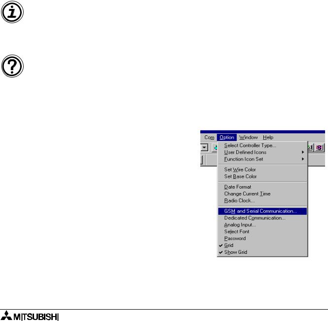
1)Click “Option” on the Menu Bar, and choose “GSM and Serial Communication...”.
12-1

α Series Simple Application Controllers |
Setting for Computer Link (AL2-14MR-*, AL2-24MR-*) 12 |
|
|
2)Click “Others” radio button.
3)Click “OK” button to complete the GSM & Serial Communication Window.
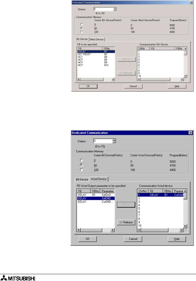
4)Click “Option” on the Menu Bar, and choose “Dedicated Communication...”
12-2

α Series Simple Application Controllers |
Setting for Computer Link (AL2-14MR-*, AL2-24MR-*) 12 |
|
|
5)Set station number.
6)Choose number of the communication data for computer link from the Communication Memory.
7)Select the Communication Bit device in Bit Device Tab.
To set bit device:
a)Choose the bit device in the “FB to be specified”.
b)Choose the VB Number in the “Communication Bit device”.
c)Click the Set button
d)If completing the setting for bit device(s), continue a) ~ c).
e)Click the Word Device Tab.
8)Select the Communication Word device in Word Device Tab.
a)Choose the word device in the “FB Word Output parameter to be specified”.
b)Choose the VB Number in the “Communication Bit device”.
c)Click the Set button
d)If completing the setting for word device(s), continue a) ~ c).
9)Click “OK” button to complete Dedicated Communication Window.
12-3

α Series Simple Application Controllers |
Setting for Computer Link (AL2-14MR-*, AL2-24MR-*) 12 |
|
|
10)Write data to the α2 series, and the power supply of α2 series needs to be turned OFF to ON to support computer link.
12-4

α Series Simple Application Controllers |
Information about AS-interface Programming 13 |
|
13.Information about AS-interface Programming
AS-interface modules are available for the following module and can be programmed with the AL-PCS/WIN-E. The following special symbols apply only to the AS-interface network. Further information about AS-interface programming can be found in α and α2 series Programming Manuals, and AL/AL2-ASI-BD Hardware Manual.
Table 13.1: Applicable α Series
|
|
|
|
|
Series |
Model Type |
|
|
|
|
|
|
α series |
AL-20M*-* |
|
|
|
|
|
|
α2 series |
AL2-14M*-*, AL2-24M*-* |
|
|
|
|
|
|
|
|
|
13-1
