


α Series Simple Application Controllers |
Function Block Diagram (FBD) Programming 6 |
|
|
6.6.3Select Signal Order (Step 4)
The Wizard will show the possible combinations of Functions Blocks. A pictorial representation will appear at the top of the screen and the function block icon connection will be shown below. Use the Up and Down arrow keys to scroll through the possible combinations. Depending upon the number and type of Function blocks chosen, dozens of possible combinations will show on screen. The first combination will be chosen as a default if no selection is made.
6.6.4Adding a Logical Condition (Step 5)
Choose to have the output conditions driven by input signals or to have them continuously driven. Flicker or Compare function block comes left most, it is displayed as shown in the right figure.
Active depending on other signals: Using Flicker or compare function
When adding, check this option, the input signal can be connected to left most Flicker or Compere function block.
Set depends on other signals:
Using Set/Reset function, and Flicker or Compare function
When adding check this option, the input signal can be connected to left most Set/ Reset function block connected to the set pin side of the Flicker or Compere function block.
Reset depends on other signals:
Using Set/Reset function, and Flicker or Compare function
When adding check this option, the input signal can be connected to left most Set/Reset function block connected to the reset pin side of the Flicker or Compere function block.
Note:
When the check mark has been added, the display is redundant, the Boolean function block is automatically added to the input pin of the left most function block.
6-21
α Series Simple Application Controllers |
Function Block Diagram (FBD) Programming 6 |
|
|
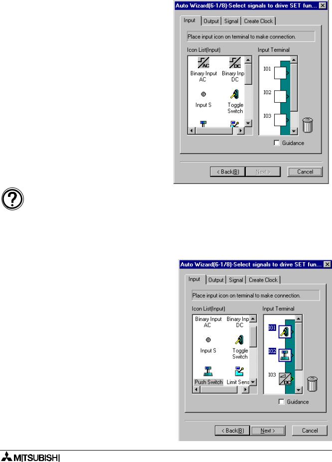
6.6.5Select Input Signals to Drive Functions (Step 6)
Choose up to 4 input signals which connects to the “Bit Input Pin” on the left most function block from the following.
-Input terminal (Input Tab)
-Output Terminal (Output Tab)
-Operation key (Signal Tab)
-System Bit (Signal Tab)
-Control Bit (Signal Tab)
-Function block (Signal Tab)
-Time Switch function block (Signal or Create Clock Tab)
Note:
•When selecting the Set/Reset function block on the step 2 and 3, the step 6 will be set twice (6-1 and 6-2). At first set for the “set depend on other signals”, at second set for the “Reset depends on other signals”.
•When no addition is intended check the “Active depend on other signals”, “Set depend on other signals” and “Reset depend on other signals” from step 5, then step 6 will not appear, thus the next step 7 appears.
1)Input Tab
Click the target Input terminal to select. When the icon has already been put on the Input terminal with the FBD base, the icon will be displayed in the Input terminal as shown.
To allocate the icon:
Click the icon from the Input icon to select the appropriate device selection, and click the Input terminal which needs to be allocated again.
To delete the icon to be allocated:
Move the Input icon to be deleted from the Input terminal to the trash bin by drag & drop.
6-22
α Series Simple Application Controllers |
Function Block Diagram (FBD) Programming 6 |
|
|
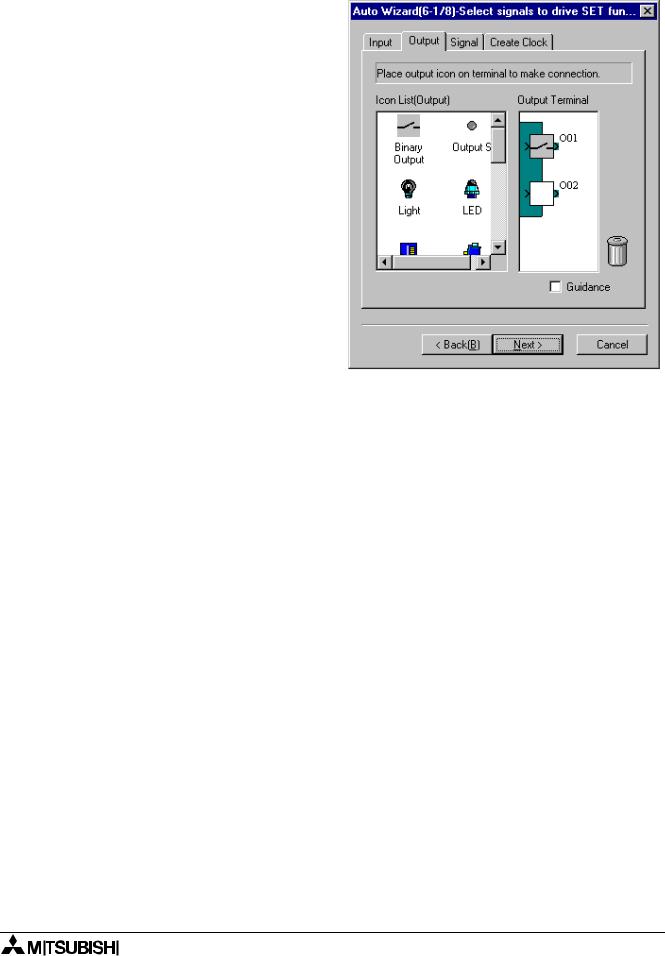
2)Output Tab
Click the target Output terminal to select the appropriate device.
When the icon has already been put on the Output terminal with the FBD base, the icon will be displayed in the Output terminal as shown.
To allocate the icon:
Click the icon from the output icons in the left of the screen list, and click the output terminal which wants to be allocated again.
To delete the icon to be allocated:
Move the output icon to be deleted from the output terminal to the trash bin by drag & drop.
6-23

α Series Simple Application Controllers |
Function Block Diagram (FBD) Programming 6 |
|
|
3)Signal Tab
Set internal signal(s) by the “New Signal” or “Start Select” from the following signals.
-Input signal with block number (by New Signal button)
-Operation key
(by Start Select button)
-System bit (by Start Select button)
-Control bit (by Start Select button)
-Input and Output for AS-interface (by Start Select button)
-Function block
(by Start Select button)
New Signal button:
Clicking this button a new input signal with appropriate block number will be add.
Start Select button:
Input signal number of the operation key, the system bit, the control bit, the input/output for AS-interface or the function block.
6-24

α Series Simple Application Controllers |
Function Block Diagram (FBD) Programming 6 |
|
|
4)Create Clock
Add output signal for new Time Switch function block, and set parameter for this time Switch function block by the “Set New TimeSwitch” button
To add new Time Switch function block:
a)Click the check box as shown “Create New TimeSwitch” to add the new Time Switch function block.
b)Click the “Set New TimeSwitch” button to set parameter for the Time Switch function block. A setting operation is identical to the parameter of the Time Switch function block set on the FBD base. Further information about parameters of each function block can be found in the programming manual and “Help” on the AL-PCS/WIN-E.
6-25