

α Series Simple Application Controllers |
Information about AS-interface Programming 13 |
|
|
13.1AS-interface Input Icon and System Bit Icon
There is an AS-interface icon available in the Input Signal Accessory Toolbar (“In” Menu).
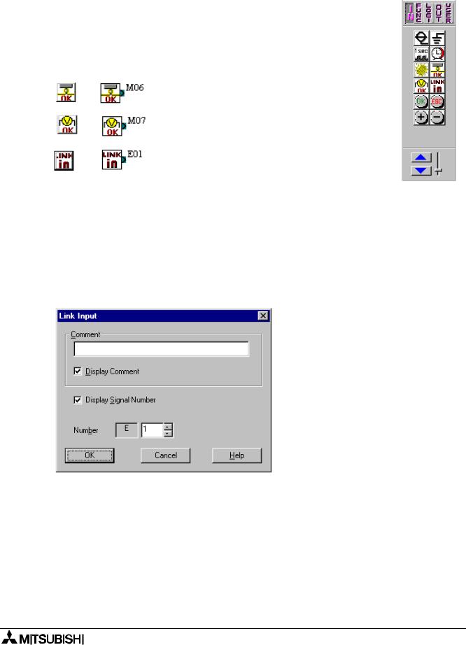
Table 13.2: AS-interface Input Icon
|
|
|
|
|
|
|
Icon on |
Icon on |
System Bit |
|
|
|
Accessory |
or Input |
Description |
|
|
|
FBD |
|
|||
|
Toolbar |
Number |
|
|
|
|
|
|
|
||
|
|
|
|
|
|
|
|
|
M6 |
“ON” when communication Error for |
|
|
|
|
AS-interface occurs |
|
|
|
|
|
|
|
|
|
|
|
|
|
|
|
|
|
M7 |
“ON” when communication Error by |
|
|
|
|
AS-interface power failure occurs |
|
|
|
|
|
|
|
|
|
|
|
|
|
|
|
|
|
E01 ~ E04 |
Input device from AS-interface master |
|
|
|
|
module |
|
|
|
|
|
|
|
|
|
|
|
|
|
|
|
|
|
|
|
|
13.1.1AS-interface Input Icon
There is an AS-interface icon available in the Input Signal Accessory Toolbar (“In” Menu). A total of 4 AS-interface “Link In” inputs (E01 ~ E04) can be added to the FBD base. The ASinterface inputs do not count towards the number of α series Inputs available.
To arrange input for AS-interface Network:
1)Click “Link in” icon in the Input Signal Accessory Toolbar (In menu), and click on the FBD window to arrange AS-interface input icon.
2)Set number of input for AS-interface network.
3)Click “OK”
13.1.2ASI System Bits Icon
The M6 and M7 are system bits dedicated strictly to the AS-interface network. These system bit for the AS-interface Network line is connected to the AL/AL2-ASI-BD for both Power and communication purposes.
13-2
α Series Simple Application Controllers |
Information about AS-interface Programming 13 |
|
|
13.2AS-interface Output Icons and Control Bit Icon
There is an AS-interface icon available in the Output Signal Accessory Toolbar (“Out” Menu).
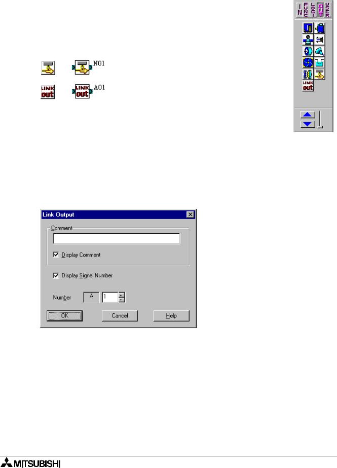
Table 13.3: AS-interface Output Icon
|
|
|
|
|
|
|
Icon on |
Icon on |
System Bit |
|
|
|
Accessory |
or Input |
Description |
|
|
|
FBD |
|
|||
|
Toolbar |
Number |
|
|
|
|
|
|
|
||
|
|
|
|
|
|
|
|
|
N1 |
OFF: Connect to AS-interface network |
|
|
|
|
ON: Unconnected to AS-interface network |
|
|
|
|
|
|
|
|
|
|
|
|
|
|
|
|
|
A01 ~ A04 |
output device from AS-interface master |
|
|
|
|
module. |
|
|
|
|
|
|
|
|
|
|
|
|
|
|
|
|
|
|
|
|
13.2.1AS-interface Output Icon
There is an AS-interface icon available in the Output Signal Accessory Toolbar (“Out” Menu). A total of 4 AS-interface “Link Out” outputs A01 ~ A04) can be
added to the FBD base. The AS-interface Outputs do not count towards the number of α series Outputs available.
To arrange input for AS-interface Network:
1)Click “Link out” icon in the Input Signal Accessory Toolbar (“Out” menu), and click on the FBD window to arrange AS-interface output icon.
2)Set number of output for AS-interface network.
3) Click “OK”
13-3

α Series Simple Application Controllers |
Information about AS-interface Programming 13 |
|
|
13.2.2Active/Passive State
The α series can be switched from an Active to a Passive state on the AS-interface network by changing the state on the N01 Control Icon. In the Active State, N01=0, communication is possible over the network. This icon can be found in the “Out” Menu next to the AS-interface “Link Out” icon.
When multiple α series are added to a network, each slave must be given an address. In order to address the slaves from the Master station, only one unaddressed slave can be active at any one time. Once a slave has an address, another passive slave can be turned to an active state to receive its address.
Please refer to the α and α2 series Programming Manuals, the AL/AL2-ASl-BD Hardware Manual and the manual for the AS-interface Network Master Controller.
13-4

α Simple Application Controllers

HEAD OFFICE: MITSUBISHI DENKI BLDG MARUNOUCHI TOKYO 100-8310 HIMEJI WORKS: 840, CHIYODA CHO, HIMEJI, JAPAN
JY992D74001J |
Effective Aug. 2005 |
(MEE) |
Specifications are subject to change without notice. |