

Color.Atlas.of.Endodontics-ublog.tk
.pdf46 |
Color Atlas o f Endodontics |
FIGURE 2-60 The most common modification, useful even when rotary NiTi instruments are not used, is to create a notch in the access that enhances visibility and straight-line access to the MB 2 canal. In most cases, creating this notch also provides a cleaner path of insertion for the DB canal.
FIGURE 2-61 The amalgam buildup under the crown on this maxillary first molar exhibiting five canals encroached on access
to the MB2 canal. The area was fluted aggressively to eliminate the possibility of the rotary NiTi instruments abrading the amalgam during instrumentation and consequently creating amalgam scraps and prematurely dulling the instruments. Note the dentin apical to the amalgam.
FIGURE 2-62 In this patient with limited opening, the entire access outline was shifted to the mesial. The arrows represent the views to the canals perpendicular to the occlusal surface and from the mesial, as the clinician would see when clinically treating the tooth. Note that the arrows are the same length, but the angled arrow requires less interocclusal space.

Chapter Two Endodontic Access |
47 |
•Sony DCR-PC 100 DV microscope-mounted camera using the MemoryStick and imported to the Trophy software
•Sony DCR-PC 100 DV microscope-mounted camera using the S-Video output connected to a Trophy video capture board
•Nikon Coolpix 950 microscope-mounted camera using compact flash card and imported to the Trophy software
•DMD Telicam Elite connected to a Trophy video capture board
Images have been globally adjusted and spot adjusted for brightness, contrast, and color balance. Images have also been rotated, flipped, and cropped and converted from the RGB colorspace used in CRTs to the CMYK palette used in printing. These adjustments were made to highlight the relevant anatomic features; correct for the differences among cameras, light sources, and capture mechanisms; and overcome the limitations of technology when working down in deep, dark holes.
References
1.Walton R: Access preparation and length determination. In Walton RE, Torabinejad M, editors: Principles and practice of endodontics, Philadelphia, 2002, WB Saunders.
2.Green D: Double canals in single roots, J Oral Surg 35:689, 1973.
3.American Association of Endodontists: Endodontic case difficulty assessment form, Chicago, American Association of Endodontists.
4.Stropko JJ: Canal morphology of maxillary molars: clinical observations of canal configurations, J Endodon 25(6):446, 1999.
5.Vertucci FJ: Root canal anatomy of human permanent teeth, Oral Surg Oral Med Oral Pathol Oral Radiol Endod 58:589, 1984.
6.Kasahara E et al: Root canal system of the maxillary central incisor, J Endodon 16(4):158, 1990.
7.Burns RC, Herbranson EJ: Tooth morphology and cavity preparation. In Cohen S, Burns RC, editors: Pathways of the pulp, ed 8, St Louis, 2002, Mosby.
8.Carns EJ, Skidmore AE: Configuration and deviation of root canals of maxillary first premolars, J Oral Surg 36:880, 1973.
9.Kulild JC, Peters DD: Incidence and configuration of canal systems in the mesiobuccal root of maxillary first and second molars, J Endodon 16(7):311, 1990.
10.Mauger MJ et al: Ideal endodontic access in mandibular incisors, J Endodon 25(3):206, 1999.
11.Benjamin KA, Dowson J: Incidence of two canals in human mandibular incisor teeth, J Oral Surg 38:122, 1974.
12.Clements RE, Gilboe DB: Labial endodontic access opening for mandibular incisors: endodontic and restorative considerations,
J Can Dent Assoc 57:587, 1991.
13.Baisden MK, Kulild JC, Weller RN: Root canal configuration of the mandibular first premolar, J Endodon 18(10):505, 1992.
14.Hartwell G, Bellizzi R: Clinical investigation of in vivo endodontically treated mandibular and maxillary molars, J Endodon 8(12):555, 1982.
15.Melton DC, Krell KV, Fuller MW: Anatomical and histological features of C-shaped canals in mandibular second molars, J Endodon 17(8):384, 1991.
16.Weine FS: The C-shaped mandibular second molar: incidence and other considerations. Members of the Arizona Endodontic Association, J Endodon 24(5):372, 1998.

50 |
Color Atlas o f Endodontics |
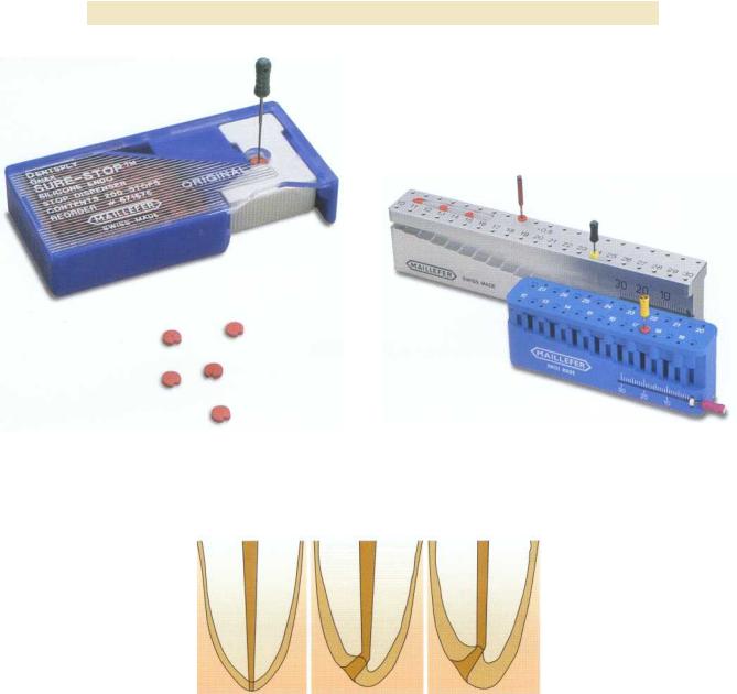
FIGURE 3-1 Sure-Stop silicone endodontic stop dispenser. (Courtesy Dentsply Maillefer,Tulsa, OK.)
FIGURE 3-2 Endo-M-Bloc and File-mate stop setting and measuring devices. (Courtesy Dentsply Maillefer,Tulsa, OK.)
FIGURE 3-3 Chronological cementum deposition with subsequent deviation of the apical foramen. (Redrawn from KuttlerY: Microscopic investigation of root apexes, JAm DentAssoc 50:544, 1955.)
APICAL REFERENCE POINT
Where should endodontic treatment terminate? In 1916 the theory was advanced that pulp tissue extends through the apical foramen.11 Later, Grove contradicted this and stated that the tissue in the foramen is periodontal tissue, not pulp tissue, and is important for cementum formation via periodontal ligament cells after pulp tissue remova1. 12 Grove later discussed the importance of always filling the root canal to the dentinocemental junction (DCJ), which is "a definable point in all cases." 13,14 This was based on a few histologic sections taken from extracted immature teeth.
Coolidge also evaluated several histologic sections of root ends and described the DCJ as an imaginary
line. He stated that the removal of pulp tissue near the apical foramen is required for success, not pulp removal at the DCJ or any other definable point." Grove was also challenged by several other authors who reported that the DCJ is rarely a definable point in teeth. After examining more precise histologic data, they found that not only is the DCJ rarely located near apical constriction, but also that it occasionally is found on the external root surface because of root resorption and ana-
tomic variation. 16,17
The first extensive investigation of root apex anatomy was performed by Kuttler in 1955. 18 He evaluated 268 teeth (primarily from cadavers) from which 402 root ends were split through the apical foramen and

Chapter Three Length Determination |
51 |
FIGURE 3-4 Radiograph (A) and histologic section (B) of ideal |
FIGURE 3-5 Radiograph (A) and histologic section (B) of tooth |
apical constriction on tooth #7. |
#29 with a slight apical constriction. |
examined. He reported several findings, including deviation of the center of the foramen further from the apical vertex with age and subsequent cementum deposition ( Figure 3-3). The minor diameter was usually found in dentin. Kuttler concluded that the root canal should be filled as far as 0.5 mm from the foramen because the average distance from the minor diameter to the foramen is roughly 0.6 mm. Only 40% to 47% of apices had two DCJs at the same level on the sections.
Burch confirmed Kuttler's results by finding the average deviation of the apical foramen from the anatomic apex to be 0.59 mm in 877 teeth. He found that 40% of these deviated in a buccal or lingual direction, making
radiographic detection difficult. 19 Others have reported average distances as large as 0.8 mm, 0.99 mm, 0.9 mm, and 0.86 mm.20-23 Different tooth types have variable anatomic configurations. The average distance between the major foramen and the apex of anterior teeth has been reported to be 0.26 mm, with 31 % opening directly at the apex. For molars the average distance is 0.44 mm, with 39% opening directly at the apex .24,25
The variability in apical canal anatomy makes working length determination extremely challenging. Canal variations range from an ideal apical constriction (Figure 3-4), to slight apical constriction (Figure 3-5), to no constriction at all (Figure 3-6). Frequently canals can

52 |
Color Atlas o f Endodontics |
A B
FIGURE 3-6 Radiograph (A) and histologic section (B) of palatal root of tooth #15 with no apical constriction.
A B
FIGURE 3-7 Radiograph (A) and histologic section (B) of mesial root of tooth #19 with apical foramen well short of radiographic apex.
terminate several millimeters from the radiographic apex (Figures 3-7 and 3-8). This variability in apical canal anatomy has been reported by Dummer, who examined 270 extracted teeth and categorized the apical anatomy into five types of constrictions 26 (Figure 3-9):
1.Typical single constriction
2.Tapering constriction with the narrowest portion near the actual apex
3.Several constrictions
4.Constriction followed by a narrow, parallel canal
5.Complete blockage of the apical canal by secondary dentin
Besides causing cementum deposition, resorptive processes can also affect the relationships of the apical anatomy and decisions regarding endodontic treatment termination (Figures 3-10 and 3-11). Malueg examined

Chapter Three Length Determination |
53 |
A B
FIGURE 3-8 Radiograph (A) and histologic section (B) of mesial root of tooth #19 with apical foramen well short of radiographic apex.
FIGURE 3-9 Dummer's classifications of apical canal anatomy. (Redrawn from Dummer PMH, McGinn JH, Rees DG: The position and topography of the apical canal constriction and apical foramen, Int Endod J 17:192, 1984.)
FIGURE 3-10 Radiograph (A) and histologic section (B) of mesial root of tooth #31 with inflammatory root resorption.

54 |
Color Atlas o f Endodontics |
A B
FIGURE 3-11 Radiograph (A) and histologic section (B) of distal root of tooth #30 with inflammatory root resorption.
49 root ends in 40 teeth with scanning electron microscopy and described the amount of apical resorption occurring with preextraction pulpal and periapical diagnosis. 27 Out of 25 roots with necrotic pulps, 18 demonstrated funneling (root resorption extending into the internal surface of the foramen), a number significantly higher than that observed in vital pulps. Therefore "the status of the pulp and periapical tissues should be considered when determining the length for preparation or obturation."27 Traumatic tooth injury also can cause root resorption. Approximately 20% to 40% of the root structure must be demineralized before buccal or lingual root resorption can be detected radiographically.28 Some researchers suggest calculating the working length 1 mm short of the radiographic apex with normal apical anatomy, 1.5 mm short with bone but no root resorption, and 2 mm short with bone and root resorption. 29
METHODS OF DETERMINING
WORKING LENGTH
Methods for determining working length include using average root lengths from anatomic studies, preoperative radiographs, tactile detection, or the "eye twitch" response. Other common methods include bleeding on a paper point and using working length radiographs made with a variety of different film types or digital sensors, electronic apex locators, or any combination of the above.
Ideally, the clinician should measure working length after attaining straight line access to the apical third of the root canal system. The length may change slightly after working length determination because of the elimination
of the coronal deflection of the working length . 30, 8 This is especially true in the mesial canals of molars, where much of the total curvature of the canal is eliminated after the cervical bulge is removed. Moreover, attaining straight line access and preflaring the canal space greatly improves tactile detection of the apical constriction.31
Radiography
Since Wilhelm Roentgen's discovery of the x-ray in 1895, continued efforts have been made to reduce the amount of ionizing radiation exposure to the patient while improving or maintaining image quality. Otto Walkhoff's production of the first dental radiograph required 25 minutes of exposure time. 32 Current methods to reduce radiation exposure include using the paralleling technique instead of the bisecting angle technique and employing rectangular long cone techniques, faster radiographic film, digital radiographic techniques, and electronic apex locators to assist in endodontic treatment." Rectangular collimation can decrease the radiation exposure by 40% compared with a 6 cm round beam, E-speed film can decrease exposure by 40% over D-speed film, and constant potential x-ray units can decrease exposure by 40% compared with conventional alternating current units. 34
As steps are made to reduce patient radiation exposure, the quality of working length determination must not be sacrificed . 35 When radiographs are used to deter mine working length, the quality of the image is important for accurate interpretation. Paralleling techniques have been demonstrated as superior to bisecting angle radiographic techniques in interpretation of length determination and reproduction of apical anatomy. 16-38 As

Chapter Three Length Determination |
5 5 |
the angle increases away from parallel, the quality of the i mage decreases.37 This occurs because as the angle is increased, the tissue that the x-rays must pass through includes a greater percentage of bone mass and root anatomy becomes less discernible. To limit some of these problems, the "modified paralleling" technique has been suggested by Walton; in this technique the central beam is oriented perpendicular to the radiographic film, but not to the tooth. 29
Several choices are available regarding radiographic film and processing. No significant difference has been demonstrated in the diagnostic quality of E-Plus radio graphic film compared with D-speed film. 39-43 For this reason, E-Plus film should be used to reduce radiation exposure to the patient. Rapid processing chemicals are also used in endodontics to expedite the development of film for treatment radiographs. When tested, these rapid techniques provided similar diagnostic quality to normally processed radiographs for working length determination. 42
Parallel working length radiographs can be difficult to attain because of misorientation, shallow palatal vault, and tori. Products such as the "Endo-Ray II" (Figure 3-12) (Dentsply Rinn, Elgin, IL) may help produce more predictable results. This alignment device assists in making a parallel working length radiograph without removing the rubber dam clamp or files from the tooth. Dental students using hemostats produced acceptable radiographs in 66% of maxillary and 75% of mandibular teeth on patients undergoing endodontic treatment. When the Endo-Ray II was used, acceptable radiographs were made in 87% of maxillary and 85% of mandibular teeth .44
Because increased vertical angulation is often necessary when making maxillary radiographs, zygomatic arch interference becomes a significant problem in interpreting apical anatomy and determining working length. Approximately 42% of maxillary second molars and 20% of first molars exhibit this interference.45
An understanding of the buccal object rule (BOR) is essential to endodontic treatment. The main concept of the rule is that as the vertical or horizontal angulation of the x-ray source or tube head changes, the object buccal or closest to the tube head moves to the opposite side of the radiograph compared with the lingual object. For example, if a working length radiograph is of a maxillary first premolar with no horizontal angulation (buccal and lingual roots are superimposed) and too little vertical angulation (apex is not captured on radiograph), a new working length radiograph is necessary. To separate the buccal and lingual roots to visualize the individual working length file's relationship to the apical root structure, the clinician should place the tube head from a 20 degree mesial angulation. This captures the buccal root on the opposite or distal side of the radiograph and the lingual root on the mesial side of the radiograph. To cap-
FIGURE 3-12 Endo-Ray II film holder. (Courtesy Dentsply Rinn, Elgin, IL.)
ture the entire apical portion of the roots, the vertical angulation of the tube head should be increased from a positive, or superior, position. This is demonstrated on the radiograph as the buccal root appearing more inferior, or coronal, to the lingual root (the opposite direction of the tube head angulation) and the lingual root appearing toward the superior, or top, of the film. This rule can also be applied to locating root resorptive processes in relation to a tooth, identifying anatomic landmarks and pathosis, locating a canal in relation to a radiopaque marker such as a bur in the access, or locating the position of additional roots . 46 Additionally, to increase visualization of apical anatomy, this rule can be used to "move" anatomic landmarks such as the zygomatic process or impacted teeth .47 It also helps identify the angle at which a particular radiograph was made even if the information was not recorded. For example, the palatal root of a maxillary molar curves to the distal side and is located toward the distobuccal root rather than between the two buccal roots when the angle of the radiograph is from the mesial side. Extensive information on the BOR has been reported by Richards. 48 Other names for the BOR include the SLOB (Same Lingual, Opposite Buccal) rule, the BOMM (Buccal Object Moves Most) rule, Clark's rule, and Walton's projection . 49 Walton suggests an easy method to simplify this concept. Place two or three fingers in front of your eyes to represent the roots of a particular tooth. As you move your head to the "mesial," or for demonstration purposes to the right, while keeping your fingers in the same position, you will notice that the "buccal" object, or the finger closest to your face, will move to the "distal" or left. This is exactly the way a structure would be pro- j ected on the radiographic film and can be applied to vertical angulation in a similar fashion . 2 9
Although the individual canals can usually be deciphered by applying the BOR and knowing the angle at

5 6 |
Color Atlas of Endodontics |
FIGURE 3-13 Film placement for maxillary working length radiographs. (Redrawn from Walton RW,Torabinejad M: Principles and practice ed 3, Philadelphia, 2002, WB Saunders.)
which the radiograph was made, misinterpretation is still possible. This can be reduced by using different file types (e.g., Hedstrom, K-file) or different file sizes (e.g., 15, 25, 35) in adjacent canals.35
Preoperative periapical radiographs have been used to calculate the working length for endodontic treatment. 36 Because a magnification of about 5.4% is em ployed in the paralleling technique, 1 to 2 mm must be subtracted from the measurement on the preoperative radiographs° Pantographic radiographs have not been advocated for calculating the estimated working length because of the gross magnification of 13% to 28% that is employed.51 "Radiographic incrementation" is the process of using a millimeter grid stamped on the film or a copper grid to measure working length. Using these measurements alone can produce unfavorable results.52,36 Rather than using this method alone to measure working length, which was commonly done in the early years of endodontic treatment, this measurement can be used as an "estimated working length" that can then be confirmed by placing an endodontic instrument into the canal and taking a second radiograph. The "corrected working length" can then be calculated by adding or subtracting the distance between the instrument tip and the desired apical termination of the root. This technique was first introduced by John Ingle.5 3 When measuring the distance from the file tip to the ad- j usted stop with a metric ruler, it is important to straighten any curvatures present in the working length file to prevent misinterpretation.
When rubber dams are in place, working length radiographs can be challenging. The rubber dam frame
should be left in place to maintain isolation, but one corner of the dam can be released to facilitate placement of the film. For this reason, plastic rubber dam frames should be used in endodontic treatment.
FIGURE 3-14 Film placement for mandibular working length radiographs. (Redrawn from Walton RW,Torabinejad M: Principles and practice ed 3, Philadelphia, 2002, WB Saunders.)
Angled working length radiographs help separate overlapping canals, especially in mandibular teeth and maxillary premolars. Walton outlined the ideal orienta tion and angles for working length radiographs in maxillary and mandibular teeth (Figures 3-13 through 3-15). Maxillary anterior teeth only contain single canals, and maxillary molars require straight-on radiographs. The palatal canal is centered between the mesiobuccal and distobuccal roots in maxillary molars. When a second mesiobuccal canal (MB 2) is suspected, a mesial radiograph is often required to identify it. However, as the horizontal angulation increases, the clarity of the radicular anatomy decreases. A 20 degree mesial shift is sufficient to separate the canals while limiting distortion. When making maxillary radiographs, the operator places the film parallel to the tooth and perpendicular to the central ray and as far apical as possible. Generally the radiograph is placed at the junction of the hard and soft palate for maxillary anterior teeth and on the opposite side of the palate for maxillary posterior teeth (see Figure 3-13). Mandibular radiography also has some challenges. The radiographic film is placed as close to the tooth and as parallel to the tooth as possible to limit distortion. Generally this can be achieved by placing the film deep in the vestibule. If the patient closes the mouth slightly, the film generally can be placed more apically as the mylohyoid muscle relaxes .29
New Technology
Advances in electronics and computers are generating many treatment adjuncts in endodontics and specifically in working length determination. Careful analysis and use of these devices is crucial to provide improved patient care now and in the future. Bender stated on his ninetieth birthday celebration, "The clinical practice of yesterday's endodontics becomes the heresy of today and today's en-