

Color.Atlas.of.Endodontics-ublog.tk
.pdf142 |
Color Atlas o f Endodontics |
FIGURE 9-10 Restoration with a cast post and core. A, Endodontically treated incisor with 5 mm of gutta-percha remaining; undercuts must be removed. B, Canal space prepared with Gates Glidden burs and corresponding ParaPost drills. C, The tooth is lubricated and pattern resin is placed using a bead-brush technique. D, The coronal portion of the pattern is contoured using a fine diamond bur and high-speed handpiece with water spray.
holding the pattern firmly in the tooth. (Lubricate the tooth with a water-soluble lubricant such as SurgiLube [Figure 9-10].)
10.Building the pattern should be a two-step process. Build the internal portion of the pattern first and ensure that it can be removed before creating the entire pattern (Figure 9-11).
11.The finished pattern should be smooth and free
from voids and exhibit good resistance and retention form (Figure 9-12).
12.Sprue, invest, and cast with Type III dental alloy (Figure 9-13).
3. Perform try-in and cementation.
14.The post and core restored tooth should exhibit all the features of an ideal crown preparation (Figure 9-14).

Chapter Nine Restoration of the Endodontically Treated Tooth |
1 43 |
FIGURE 9-11 The internal portion of the pattern is built and easy |
FIGURE 9-12 The completed post and core pattern. |
removal ensured before the entire core is completed. |
|
FIGURE 9-13 The post and core pattern has been cast with Type III gold and air abraded with 50micron aluminum oxide.

1 44 |
Color Atlas o f Endodontics |
FIGURE 9-14 Tooth #5, an abutment for a fixed partial denture, was restored using a cast post and core. A, Prepared tooth. B, Cemented cast post and core; note the 360° of remaining tooth structure for ferrule.
Fabrication o f an Indirect Cast
Post and Core Pattern
Follow steps 1 through 7 described previously for fabrication of a direct cast post and core pattern, then perform the following steps:
8.Place into the prepared post space the ParaPost XP impression post (P-743) corresponding to the last drill used. If necessary, adjust the length of the impression post so the post does not contact the impression tray.
9.Take an impression with an elastomeric impression material. Make sure the anti-rotational box is filled with impression material.
10.Pour a model and fabricate a precision removable die.
11.Place the corresponding ParaPost XP burnout post into the post space of the model.
12.Complete the core pattern and remove it from the model. The finished pattern should be smooth and free from voids and exhibit good resistance and retention form.
13.Sprue, invest, and cast with Type III dental alloy.
The Provisional Post Crown
The temporary post crown is a potential weak link in the restoration of endodontically treated teeth because it may permit bacteria to enter the radicular space. Therefore a temporary post crown should be used for as short a time as possible.' ,' A temporary post crown may be fabricated from a variety of provisional crown materials but should always have well-fitting margins to hinder leakage.
Fabrication o f the Provisional Post Crown
After the custom post and core pattern is made, a provisional post such as the one provided in the ParaPost system can be used. This type of post provides good adaptation to the prepared canal and prevents leakage. The steps for fabricating a direct pattern are outlined in the following Clinical Technique.
1.Lubricate the tooth and adjacent teeth with a watersoluble lubricant such as SurgiLube.
2.Place a ParaPost XP aluminum temporary post (P-746) that corresponds with the planned final post size into the prepared canal space.
3.If a provisional crown was made previously, check that it fits over the post and seats fully into the proper occlusion. If it does not seat fully, remove material from the inside of the provisional crown or shorten the provisional post at the apical end.
4.Flow provisional crown reline material around the post, allowing it to fill any existing space.
5.Flow reline material into the provisional crown as well and seat it onto the post, allowing it to set but removing it before the final set to prevent it from locking into adjacent tooth undercuts.
6.When the provisional crown is removed, the post is incorporated into the internal surface.
7.Trim away excess reline material and evaluate margins for adequate seal and fit.
8.If discrepancies are evident, reline the margins to correct them. The finished provisional restoration should mimic the planned definitive restoration in contour and fit.

Chapter Nine Restoration of the Endodontically Treated Tooth |
1 45 |
FIGURE 9-15 A, A Micro-Etcher allows air abrasion surface treatment with 50-micron aluminum oxide. B, The clinician should air abrade the entire surface of the cast post and core before cementation to increase retention.
9.Cement the provisional post crown with provisional cement. The use of non-eugenol cement such as TempBond NE (Kerr USA, Romulus, MI) is recommended because the provisional post crown will need to be relined after cementation of the cast post and core. Eugenol has been demonstrated to inhibit the set of some provisional crown materials. To preserve the integrity of the post space, apply temporary cement only to the margins of the crown; do not place any cement into the post space or on the post.
10.If a provisional crown was not made previously, a similar technique using some type of matrix such as a vacuum-formed polystyrene matrix or polyvinyl siloxane putty matrix may be used to create a crown form around the post and remaining tooth.
11.A large endodontic file can be substituted for the provisional ParaPost post.
Post Cementation
Prefabricated posts and custom cast posts may be cemented with a variety of luting agents. Zinc phosphate has a long history of clinical effectiveness and is still frequently employed. Although it is more time consuming to mix and proper technique is essential, it has been reported to be least affected by eugenol compared with other cements. 44 An additional advantage to zinc phosphate is the potential for removal of the post with ultrasonic instrumentation if the tooth requires retreatment
or the post fractures. Eugenol has been shown to significantly reduce the retention of posts cemented with some resin cements and recommendations have been made to irrigate the post space with ethyl alcohol or etch with 37% phosphoric acid gel to remove the eugenol residue. 45 Other choices include glass ionomer and composite resin cements. When using glass ionomer, the clinician should consider the capsulated form instead of the hand-mixed variety. Because of its consistent powder-to- liquid ratio the capsulated glass ionomer has been shown to contribute to significantly increased retention compared with the hand-mixed form . 46 Resin ionomer hybrid cements should probably be avoided for post cementation because their tendency to expand may place undue pressure on the tooth root. One study evaluating the retention of posts with resin, glass ionomer, and hybrid cements revealed disappointing results for the hybrids compared with the resin and glass ionomer cements. 47 Composite and glass ionomer luting agents are not easily removed when retreatment is required.
To enhance retention, the surface of the post can be micro-roughened before cementation with 50-micron aluminum oxide and a micro air abrasive unit (MicroEtcher, Danville Engineering Inc., Danville, CA) with 60 p.s.i. air pressure (Figure 9-15). 48 Before cementation of the definitive crown, the cast custom core may be treated with the micro abrasive unit intraorally. This removes residue from the temporary cement and leaves a clean, micro-roughened surface for final cementation. The

1 46 |
Color Atlas o f Endodontics |
tooth should be irrigated and dried with paper points before cementation to remove residue from the canal space preparation. The EndoEze System by Ultradent (South Jordan, Utah) features small capillary tips that can be attached to high-volume suction to remove irrigant from the post space efficiently and effectively. This system removes excess moisture but does not desiccate dentin, which is important particularly when resin cement is used (Figure 9-16). A single paper point can then be used
to verify the absence of irrigant.
Installation stress during cementation should be minimized. Although tapered posts tend to be self-venting, placement of a parallel post can generate hydrostatic backpressure. Venting of the post should be considered to allow excess cement to escape during the cementation process, thereby relieving cementation pressure. Some post systems have vents incorporated into the post design. Alternatively, a vent may be placed along the side of the post using a '/ round carbide bur. The clinician should also consider hydrostatic pressure when selecting a cement for the post. A study by Morando et a1 49 examined posts cemented with three different luting agents: resinous cement, glass ionomer cement, and zinc phosphate cement. The mean hydrostatic pressures (p.s.i.) were recorded. Zinc phosphate cement created substantially greater hydrostatic pressure than either the resinous or glass ionomer cements. Therefore, venting may be particularly important during use of zinc phosphate cement.
Restoration o f Endodontic Access through Full-Coverage Crowns
Endodontic treatment occasionally needs to be performed through an existing crown. In this situation, root canal treatment is more challenging. The restorative den-
FIGURE 9-16 The capillary suction tip in the EndoEze System allows efficient and effective removal of irrigant from the post
space.
tist must replace tooth structure removed during access opening and repair the void left in the crown. A decision must be made regarding whether the crown should be restored or replaced. Although endodontic access preparation can decrease retention of a crown, retention can be regained by subsequent placement of an appropriate restoration. 50,51 Amalgam is generally used to restore endodontic access through a cast gold crown. The current trend to place all-ceramic crowns on posterior teeth creates an esthetic dilemma. If the crown does not fracture during the access procedure, the patient probably will not want an alloy in the access cavity. In this situation, alloy may be still placed in the chamber, much as an amalcore would be placed. The last 2 mm of coronal opening is then treated as a porcelain repair. The porcelain is etched and receives a silane application, and composite is placed to restore the occlusal surface in a manner that mimics the original ceramic crown material. With this technique, amalgam provides a coronal seal over the root canal filling and the patient receives an esthetic restoration.
SUMMARY
Endodontically treated teeth do not appear to exhibit physical and mechanical properties that are significantly different from those of vital teeth. Loss of coronal structure is a major concern. Numerous techniques are available to restore the endodontically treated tooth. A significant factor in any technique is incorporation of a 1.5 to 2 mm ferrule. Success does not totally depend on the technique employed. Numerous factors such as remaining tooth structure, occlusal forces, and the function and periodontal status of the tooth are important. The clinician must consider all these factors when choosing a method for restoration.
References
1.Gutman JL, Tidwell E: Restoring endodontically treated teeth, Texas Dent J 114:14, 1997.
2.Saunders WP, Saunders EM: Corona] leakage as a cause of failure in root-canal therapy: a review, Endod Dent Traumatol 10:105,
1994.
3.Bateman LA: Fundamentals o f fixed prosthodontics, Carol Stream,
IL, 1997, Quintessence.
4.Nyman S, Lindhe J: A longitudinal study of combined periodontal and prosthetic treatment of patients with advanced periodontal disease, J Periodontol 50:163, 1979.
5.Sorensen JA, Martinoff JT: Endodontically treated teeth as abutments, J Prosthet Dent 53:631, 1985.
6.Hatzikyriakos AH, Reisis Gl, Tsingos N: A 3-year postoperative clinical evaluation of posts and cores beneath existing crowns, J Prosthet Dent 67:454, 1992.
7.Papa J, Cain C, Messer HH: Moisture content of vital vs. endodontically treated teeth, Endod Dent Traumatol 10:91, 1994.
8.Huang TJ, Schilder H, Nathanson D: Effects of moisture content and endodontic treatment on some mechanical properties of human dentin, J Endod 18:209, 1992.

Chapter Nine Restoration o f the Endodontically Treated Tooth |
1 47 |
9.Reeh ES, Messer HH, Douglas WH: Reduction in tooth stiffness as a result of endodontic and restorative procedures, J Endod 15:512, 1989.
10.Sorensen JA, Martinoff JT. Intracoronal reinforcement and coronal coverage: a study of endodontically treated teeth, J Prosthet Dent 51:780, 1984.
11.Lovdahl PE, Nicolls JI: Pin-retained amalgam cores vs. cast-gold dowel-cores, J Prosthet Dent 38:507, 1977.
12.Goodacre CJ, Spolnik KJ: The prosthodontic management of en-
dodontically treated teeth: a literature review. Part 1. Success and failure data, treatment concepts, J Prosthod 4:243, 1994.
13.Leary JM, Aquilino SA, Svare CW: An evaluation of post length within the elastic limits of dentin, J Prosthet Dent 57:277, 1987.
14.Lu YC: A comparative study of fracture resistance of pulpless teeth, Chin Dent J 6:26, 1987.
15.Guzy GE, Nicholls JI: In-vitro comparison of intact endodonti-
cally treated teeth with and without endo-post reinforcement,
J Prosthet Dent 42:39, 1979.
16.Trope M, Maltz Do, Tronstad L: Resistance to fracture of re-
stored endodontically treated teeth, Endod Dent Traumatol 1:108, 1985.
17.Turner CH: Post-retained crown failure: a survey, Dent Update 9:221, 1982.
18.Newburg RE, Pameijer CH: Retentive properties of post and core systems, J Prosthet Dent 36:636, 1976.
19.Felton DA et al: Threaded endodontic dowels: effect of post design on incidence of root fracture, J Prosthet Dent 65:179, 1991.
20.Standlee JP, Caputo AA, Hanson EC: Retention of endodontic
dowels: effects of cement, dowel length, diameter, and design,
J Prosthet Dent 39:401, 1978.
21.Tjan AH, Whang SB: Resistance to root fracture of dowel chan-
nels with various thicknesses of buccal dentin walls, J Prosthet Dent 53:496, 1985.
22.Trabert KC, Caputo AA, Abou-Ross M: Tooth fracture-a comparison of endodontic and restorative treatments, J Endod 4:341, 1978.
23.Haddix JE et al: Post preparation techniques and their effect on the apical seal, J Prosthet Dent 64:515, 1990.
24.Eckerbom M, Magnusson T, Martinson T: Prevalence of apical periodontitis, crowned teeth and teeth with posts in a Swedish population, Endod Dent Traumatol 7:214, 1991.
25.Kvist T, Rodin E, Reit C: The relative frequency of periapical lesions in teeth with root canal-retained posts, J Endod 15:578, 1989.
26.Nixon C, Vertucci FJ, Swindle R: The effect of post space preparation on the apical seal of root canal obturated teeth, Todays FDA 3:1C, 1991.
27.McClean A: Criteria for the predictably restorable endodontically treated tooth, J Can Dent Assoc 64:652, 1998.
28.Sorenson JA, Engelman MJ: Ferrule design and fracture resistance of endodontically treated teeth, J Prosthet Dent 63:529, 1990.
29.Goodacre CJ, Spoolnik KJ: The prosthodontic management of en-
dodontically treated teeth: a literature review. Part II. Maintaining the apical seal, J Prosthod 4:51, 1995.
30.Mattison GD et al: Effect of post preparation on the apical seal,
J Prosthet Dent 51:785, 1984.
31.Schnell FJ: Effect of immediate dowel space preparation on the apical seal of endodontically filled teeth, Oral Surg 45:470, 1978.
32.Madison S, Zakariasen KL: Linear and volumetric analysis of apical leakage in teeth prepared for posts, J Endod 10:422, 1984.
33.Zmener O: Effect of dowel preparation on the apical seal of endodontically treated teeth, J Endod 6:687, 1980.
34.Camp LO, Todd MJ: The effect of dowel preparation on the apical seal of three common obturation techniques, J Prosthet Dent 50:664, 1983.
35.Cohen S, Burns RC: Pathways of the pulp, ed 4, St Louis, 1987, Mosby.
36.Trabert KC, Cooney JP: The endodontically treated tooth: restorative concepts and techniques, Dent Clin North Am 28:923, 1984.
37.Gagauff AG: Effect of crown lengthening and ferrule placement
on static load failure of cemented cast post-cores and crowns,
J Prosthet Dent 84:169, 2000.
38.Rosenstiel SF, Land MF, Fujimoto J: Contemporary fixed prostho-
dontics, ed 3, St Louis, 2001, Mosby.
39.Tjan AHL, Chin J: Microleakage of core materials for complete cast gold crowns, J Prosthet Dent 61:659, 1989.
40.Nayyar A, Walton R, Leonard L: An amalgam coronal-radicular
dowel and cone technique for endodontically treated posterior teeth, J Prosthet Dent 43:511, 1980.
41.Clark J: Clinical dentistry, Philadelphia, 1983, Harper and Row.
42.Kane JJ, Burgess JO, Summitt JB: Fracture resistance of amalgam coronal-radicular restorations, J Prosthet Dent 63:607, 1990.
43.Kakehashi Y et al: A new all-ceramic post and core system: clinical, technical, and in vitro results, Int J Periodont Restor Dent 18:586, 1998.
44.Dilts WE et al: Effect of zinc oxide eugenol on shear bond strengths of selected core/cement combinations, J Prosthet Dent 55:206,1986.
45.Tjan AHL, Nemetz H: Effect of eugenol-containing endodontic sealer on retention of prefabricated posts luted with an adhesive composite resin cement, Quintessence Int 23:839, 1992.
46.Mitchell CA, Orr JF, Russell MD: Capsulated versus hand-mixed glass-ionomer luting cements for post retention, J Dent 26:47, 1998.
47.Love RM, Purton DG: Retention of posts with resin, glass ionomer and hybrid cements, J Dent 26:599, 1998.
48.Williamson RT. Cast core pre-cementation preparation, J Prosthet Dent 73:320, 1995.
49.Morando G, Leupold RJ, Meiers JC: Measurement of hydrostatic pressures during simulated post cementation, J Prosthet Dent 74:586, 1995.
50.McMullen AF, Himel VT, Sarkar NK: An in vitro study of the effect endodontic access preparation has upon the retention of
porcelain fused to metal crowns of maxillary central incisors, J Endod 15:154, 1989.
51.Yu YC, Abbott PV: The effect of endodontic access cavity prepa-
ration and subsequent restorative procedures on incisor crown retention, Aust Dent J 39:247, 1994.


150 |
Color Atlas of Endodontics |
FIGURE 10-1 Skull specimen demonstrating the maxillary anterior osseous structures.
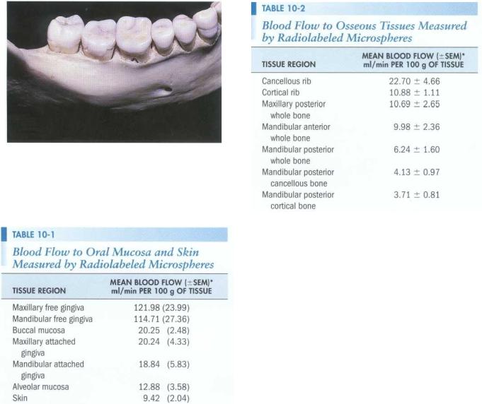
FIGURE 10-2 Skull specimen demonstrating the maxillary posterior region. Note the relationship of the zygomatic process and the maxillary first and second molars.
FIGURE 10-3 Palatal view demonstrating the incisive canal and the greater palatine foramen.
FIGURE 10-4 The mandibular anterior region of the mandible. Note the labial inclination of the incisors and the tendency for convergence of the roots.
alveolar nerve, and mental nerve. In addition, the thickness of bone in the maxillary and mandibular posterior areas can make access difficult.
Surgical procedures involving the maxillary anterior teeth are not usually complicated by the proximity of the roots to vital structures such as nerves and major vessels; moreover, the facial cortical bone is often thin. Root morphology is not complex because the teeth have only one canal (Figure 10-1). In the premolar and molar regions, the root anatomy becomes more complicated and the bone thickens. The premolars may exhibit one, two, or three roots that are often divergent. Even teeth with only one root may have more than one canal. In the posterior region the zygoma may prevent access to the buccal roots of the molars (Figure 10-2). This is especially important in treatment decisions regarding the mesiobuccal root, which is often broad and has a significant extension toward the palate. Often the roots of the maxillary molars are in proximity to the sinus. Strategic structures of the
palate include the incisive neural vascular bundle and greater palatine nerve and vessels (Figure 10-3).
The cortical plate is significantly thicker in the mandible than it is in the maxilla (Figure 10-4). In the anterior area the teeth are often inclined facially, with the roots tipped lingually in the alveolar process. In addition, the roots tend to converge apically, placing them in close proximity (see Figure 10-4). Surgery in the premolar region is complicated by the presence of the mental foramen and nerve. The root canal anatomy of these teeth is often complex, with one, two, or three canals present. In the posterior region the buccal shelf becomes prominent, increasing the thickness of bone (Figure 10-5). As the bone thickness increases, access to the broad buccal-lingual roots of the mandibular molars becomes more difficult. Moreover, the roots may approximate the mandibular canal, and flap reflection must take into consideration the location of the mental foramen (see Figures 10-4 and 10-5). Mandibular second
Chapter Ten Endodontic Surgery |
151 |
FIGURE 10-5 A mandible demonstrating the external oblique ridge and the mental foramen. Note the way the thickness of the osseous tissues on the buccal aspect increases in the second and third molar region.
Modified from Squier CA, Nanny D: Measurement of blood flow in the oral mucosa and skin of rhesus monkey using radiolabeled microspheres, Arch Oral Biol 30:313, 1985.
*SEM, Standard error of mean.
molars are closest to the mandibular canal, followed by the second premolars. The mesial root of the mandibular first molar is farthest from the canal. The path of the mandibular canal follows an S-shaped curve in one third of the cases: lying buccal to the distal root of the second molar, crossing to the lingual below the mesial root of the second molar, and then running lingual to the first molar before crossing back to the buccal apical to the second premolar.5
Oral tissues are highly vascularized and have significantly greater blood flow than skin tissues (Tables 10-1 and 10-2).6-9 Within the oral tissues, high blood flow is correlated with the thickness of the epithelium.$ The primary blood supply for the gingival tissues comes from vertically oriented vessels in the alveolar mucosa.10, 11
Modified from Johnson WT et al: Measurement of blood flow to osseous tissue in dogs using the radiolabeled microsphere method, Comp Biochern Physiol 106A:649,1993.
*SEM, Standard error of mean.
Knowledge of the microvasculature permits the placement of vertical releasing incisions that do not compromise blood supply to the reflected tissue and that decrease bleeding by running parallel with the vessels.
Blood flow to the anterior and posterior maxilla and anterior mandible does not appear to have significant differences; however, blood flow to the posterior mandible is less than that to the other structures. 9
ARMAMENTARIUM
Surgical treatment requires a unique set of instruments and materials (Figures 10-6 through 10-13). The basic tray set-up is as follows:
Mouth mirror
Explorer
Periodontal probe
Millimeter ruler
Cotton tip applicators
Gauze
Cotton forceps
Surgical blades and handle
Spoon excavator
Periosteal elevators
Surgical suction tip and stylet
Hemostat
Micro amalgam carrier
Condenser and carver
Aspirating syringe, needle, and anesthetic
Irrigating syringe bowl and sterile saline
Needle holder

152 |
Color Atlas o f Endodontics |
FIGURE 10-b A conventional high-speed handpiece and a slowspeed microsurgical handpiece.
FIGURE 10-8 A conventional mouth mirror and various microsurgical mirrors.
FIGURE 10-7 Ultrasonic tips.
FIGURE 10-9 Microsurgical blades.
FIGURE 10-10 A Stropko irrigating device (EIE/Analytic Technology, San Diego, CA).
FIGURE 10-11 A Messing gun (Produits Dentaires, S.A., Vevey, Switzerland).