
Whats A Microcontroller v3
.0.pdf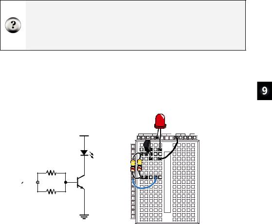
Electronic Building Blocks · Page 291
Your Turn – Switching the Transistor On/Off
If all you want to do is switch a transistor on and off, you can use the circuit shown in Figure 9-4. When the BASIC Stamp sends a high signal to this circuit, it will make it so that the transistor conducts as much current as if you adjusted the potentiometer for maximum brightness. When the BASIC Stamp sends a low signal to this circuit, it will cause the transistor to stop conducting current, and the LED should emit no light.
What’s the difference between this and connecting an LED circuit to an I/O pin?
BASIC Stamp I/O pins have limitations on how much current they can deliver. Transistors have limitations too, but they are much higher. In the Process Control Student Guide, a transistor is used to drive a small DC fan. It is also used to supply large amounts of current to a small resistor that is used as a heating element. Either of these two applications would draw so much current that they would quickly damage the BASIC Stamp, but the transistor takes it in stride.
9Build the circuit shown in Figure 9-4.
9Write a program that sends high and low signals to P8 twice every second. HINT: LedOnOff.bs2 from Chapter 2 needs only to be modified to send high/low signals to P8 instead of P14. Remember to save it under a new name before making the modifications.
9Run the program and verify that it gives you on/off control of the LED.
P8 

 100 kΩ
100 kΩ
Vdd |
Vdd |
Vin |
Vss |
|
X3 |
|
|
|
P15 |
|
|
LED |
P14 |
|
|
P13 |
|
|
|
|
P12 |
|
|
|
P11 |
|
|
|
P10 |
|
|
|
P9 |
|
|
|
P8 |
|
|
|
P7 |
|
|
|
P6 |
|
|
|
P5 |
|
|
|
P4 |
|
|
|
P3 |
|
|
|
P2 |
|
|
|
P1 |
|
|
Vss |
P0 |
|
|
X2 |
|
|
Figure 9-4
Circuit giving BASIC Stamp On/Off Control of Current to LED with a Transistor
Page 292 · What’s a Microcontroller?
ACTIVITY #2: INTRODUCING THE DIGITAL POTENTIOMETER
In this activity, you will replace the manually adjusted potentiometer with an integrated circuit potentiometer that is digitally adjusted. You will then program the BASIC Stamp to adjust the digital potentiometer, which will in turn adjust the LED’s brightness in the same way the manual potentiometer did in the previous activity.
Introducing the Digital Potentiometer
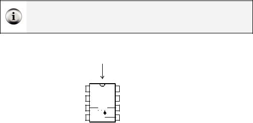
Figure 9-5 shows a pin map of the digital potentiometer you will use in this activity. This chip has 8 pins, four on each side that are spaced to make it easy to plug into a breadboard (1/10 inch apart). The manufacturer places a reference notch on the plastic case so that you can tell the difference between pin 1 and pin 5. The reference notch is a small half-circle in the chip’s case. You can use this notch as a reference for the pin numbers on the chip. The pin numbers on the chip count upwards, counterclockwise from the reference notch.
Part Substitutions: It is sometimes necessary for Parallax to make a part substitution. The part will function the same, but the label on it may be different. If you find that the digital potentiometer included in your What’s a Microcontroller Parts Kit is not labeled AD5220, rest assured that it will still work the same way and perform correctly in this activity.
Reference
Notch
|
CLK |
Vdd |
|
||||
1 |
8 |
||||||
|
|
|
|
|
|
|
|
2 |
U/D |
|
|
CS |
7 |
||
3A1 

 B1 6
B1 6
4GND  W1 5
W1 5
AD5220
Figure 9-5
AD5220 Pin Map
Use the reference notch to make sure you have the AD5220 right-side- up when building it into your circuit on the breadboard.

Electronic Building Blocks · Page 293
Here is a summary of each of the AD5220’s pins and functions:
1.CLK: The pin that receives clock pulses (low-high-low signals) to move the wiper terminal.
2.U/D: The pin that receives a high signal to make the wiper (W1) terminal move towards A1, and a low signal to make it move towards B1. This pin just sets the direction, the wiper terminal doesn’t actually move until a pulse (a low – high – low signal) is sent to the CLK pin.
3.A1: The potentiometer’s A terminal.
4.GND: The ground connection. The ground on the Board of Education and BASIC Stamp HomeWork Board is the Vss terminal.
5.W1: The potentiometer’s wiper (W) terminal.
6.B1: The potentiometer’s B terminal.
7.CS: The chip select pin. Apply a high signal to this pin, and the chip ignores all control signals sent to CLK and U/D. Apply a low signal to this pin, and it acts on any control signals it receives.
8.Vdd: Connect to +5 V, which is Vdd on the Board of Education and BASIC Stamp HomeWork Board.
The AD5220 Part Datasheet: To see the part datasheet for the AD5220: Go to www.analog.com. Enter “AD5220” into the Search field on Analog Devices’ home page, and click the Search button. Click the Data Sheets link. Click the link that reads “AD5220: Increment/Decrement Digital Potentiometer Datasheet”.
Digital Pot Controlled Transistor Parts
(1)Transistor – 2N3904
(2)Resistors – 100 kΩ (brown-black-yellow)
(1)LED – any color
(1)Digital potentiometer – AD5220
(10)Jumper wires
Building the Digital Potentiometer Circuit
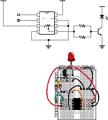
Figure 9-6 shows a circuit schematic with the digital potentiometer used in place of a manual potentiometer, and Figure 9-7 shows a wiring diagram for the circuit. The BASIC Stamp can control the digital potentiometer by issuing control signals to P5 and P6.
9 Build the circuit shown in Figure 9-6 and Figure 9-7.
Page 294 · What’s a Microcontroller?
Vdd |
|
|
|
Vdd |
|
|
AD5220 |
|
|
P6 |
1 |
CLK |
Vdd 8 |
|
P5 |
2 |
U/D |
CS 7 |
|
|
3 |
A1 |
B1 |
6 |
|
4 |
GND |
W1 |
5 |
|
|
|
Vss |
|
Vdd
100 kΩ
100 kΩ
Vss
Figure 9-6
Digital Potentiometer
Controlled Transistor
Circuit Schematic
Vdd |
Vin |
Vss |
X3 |
|
|
P15 |
|
|
P14 |
|
|
P13 |
|
Figure 9-7 |
P12 |
|
|
P11 |
|
Wiring Diagram for |
P10 |
|
|
P9 |
|
Figure 9-6 |
P8 |
|
|
|
|
|
P7 |
|
|
P6 |
AD5 |
|
P5 |
|
|
P4 |
220 |
|
P3 |
|
|
P2 |
|
|
P1 |
|
|
P0 |
|
|
X2 |
|
|
Programming Digital Potentiometer Control
Imagine that the knob on the manual potentiometer from the previous exercise has 128 positions. Imagine also that the potentiometer is in the middle of its range of motion. That means you could rotate the knob one direction by 63 steps and the other direction by 64 steps.
Let’s say you turn the potentiometer’s knob one step clockwise. The LED will get only slightly brighter. This would be the same as sending a high signal to the AD5220’s U/D pin and sending one pulse (high-low-high) to the CLK pin.
HIGH 5
PULSOUT 6, 1

Electronic Building Blocks · Page 295
Imagine next that you turn your manual potentiometer 3 steps counterclockwise. The LED will get a little bit dimmer. This would be the same as sending a low signal to the U/D pin on the AD5220 and sending three pulses to the CLK pin.
LOW 5
FOR counter = 1 TO 3
PULSOUT 6, 1
PAUSE 1
NEXT
Imagine next that you turn the potentiometer all the way clockwise. That’s the same as sending a high signal to the AD5220’s U/D pin and sending 65 pulses to the CLK pin. Now the LED should be shining brightly.
HIGH 5
FOR counter = 1 TO 65
PULSOUT 6, 1
PAUSE 1
NEXT
Finally, imagine that you turn your manual potentiometer all the way counterclockwise. The LED should emit no light. That’s the same as sending a low signal to the U/D pin, and applying 128 pulses to the CLK pin
LOW 5
FOR counter = 0 TO 127
PULSOUT 6, 1
PAUSE 1
NEXT
Example Program: DigitalPotUpDown.bs2
This example program adjusts the potentiometer up and down, from one end of its range to the other, causing the LED to get gradually brighter, then gradually dimmer.
9 Enter and run DigitalPotUpDown.bs2.

Page 296 · What’s a Microcontroller?
'What's a Microcontroller - DigitalPotUpDown.bs2
'Sweep digital pot through values.
'{$STAMP BS2}
'{$PBASIC 2.5}
DEBUG "Program Running!"
counter |
VAR |
Byte |
DO
LOW 5
FOR counter = 0 TO 127
PULSOUT 6, 1
PAUSE 10
NEXT
HIGH 5
FOR counter = 0 TO 127
PULSOUT 6, 1
PAUSE 10
NEXT
LOOP
Your Turn – Changing the Rate and Condensing the Code
You can increase or decrease the rate at which the LED gets brighter and dimmer by changing the PAUSE command’s Duration argument.
9Modify and re-run the program using PAUSE 20 and note the difference in the rate that the LED gets brighter and dimmer.
9Repeat for PAUSE 5.
You can also use a command called TOGGLE to make this program simpler. TOGGLE changes the state of a BASIC Stamp I/O pin. If the I/O pin was sending a high signal, TOGGLE makes it send a low signal. If the I/O pin was sending a low signal, TOGGLE makes it send a high signal.
9Save DigitalPotUpDown.bs2 as DigitalPotUpDownWithToggle.bs2.
9Modify the program so that it looks like the one by that name shown below.
9Run the program and verify that it functions the same way as the DigitalPotUpDown.bs2.
9Compare the number of lines of code it took to do the same job.
Electronic Building Blocks · Page 297
Running out of program memory is a problem some people encounter when their BASIC Stamp projects get large and complicated. Using TOGGLE instead of two FOR...NEXT loops is just one example of many techniques that can be used to do the same job with half the code.
'What's a Microcontroller - DigitalPotUpDownWithToggle.bs2
'Sweep digital pot through values.
'{$STAMP BS2}
'{$PBASIC 2.5}
DEBUG "Program Running!"
counter |
VAR |
Byte |
LOW 5 |
|
|
DO
FOR counter = 0 TO 127
PULSOUT 6,5
PAUSE 10
NEXT
TOGGLE 5
LOOP
Looking Inside the Digital Potentiometer
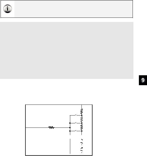
Figure 9-8 shows a diagram of the potentiometer inside the AD5220. The AD5220 has 128 resistive elements, each of which is 78.125 Ω (nominal value). All 128 of these add up to 10,000 Ω or 10 kΩ.
|
|
|
|
3 |
|
|
|
|
|
A1 |
|
|
|
Ad5220 |
|
78 Ω |
|
|
|
|
pos. 127 |
78 Ω |
|
1 |
CLK |
|
|
|
|
|
pos. 126 |
|
|
||
2 |
U/D |
W1 |
78 Ω |
|
|
5 |
|
|
Figure 9-8 |
||
|
|
|
|||
CS |
|
40 Ω pos. 125 |
|
||
7 |
|
|
Inside the AD5220 |
||
|
|
|
… |
… |
|
|
|
|
|

 78 Ω pos. 1


 78 Ω pos. 0


 B1
B1
6

Page 298 · What’s a Microcontroller?
A nominal value means a named value. Parts like resistors and capacitors typically have a nominal value and a tolerance. Each of the AD5220’s resistive elements has a nominal value of 78.125 Ω, with a tolerance of 30% (23.438 Ω) above or below the nominal value.
Between each of these resistive elements is a switch, called a tap. Each switch is actually a group of transistors that are switched on or off to let current pass or not pass. Only one of these switches can be closed at one time. If one of the upper switches is closed (like pos. 125, 126, or 127), it’s like having the manual potentiometer knob turned most or all the way clockwise. If pos. 0 or 1 is closed, it’s like having a manual potentiometer turned most or all the way counterclockwise.
Imagine that Pos. 126 is closed. If you want to set the tap to 125, (open pos. 126 and close pos. 125), set U/D low, then apply a pulse to CLK. If you want to set the tap to Pos 127, set U/D high, and apply 2 pulses. If you want to bring the tap down to 1, set U/D low, and apply 126 pulses.
This next example program uses the Debug Terminal to ask you which tap setting you want. Then it decides whether to set the U/D pin high or low, and applies the correct number of pulses to move the tap from its old setting to the new setting.
With the exception of EEPROM Data, the next example program also has all the sections you could normally expect to find in an application program:
•Title – comments that include the filename of a program, its description, and the Stamp and PBASIC directives
•EEPROM Data – DATA declarations that store predefined lists of values in portions of EEPROM memory that are not needed for program storage
•I/O Definitions – PIN directives that name I/O pins
•Constants – CON declarations that name values in the program
•Variables – VAR declarations that assign names to portions of BASIC Stamp’s RAM memory for storing values
•Initialization – a routine that gets the program started on the right foot. In this next program, the potentiometer’s tap needs to be brought down to zero
•Main – the routine that handles the primary jobs the program has to do
•Subroutines – the segments of code that do specific jobs, either for each other, or in this case, for the main routine
Electronic Building Blocks · Page 299
Example Program: TerminalControlledDigtialPot.bs2
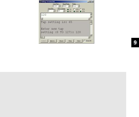
You can use this example program and the Debug Terminal to set the digital pot’s tap. By changing the tap setting on the digital pot, you change the brightness of the LED connected to the transistor that the digital pot controls. Figure 9-9 shows an example of entering the value 120 into the Debug Terminal’s Transmit windowpane while the program is running. Since the old tap setting was 65, the LED becomes nearly twice as bright when it is adjusted to 120.
Windowpanes |
Figure 9-9 |
|
Transmit |
→ |
Sending Messages |
to the BASIC Stamp |
||
|
|
Click the Transmit |
Receive |
→ |
(upper) windowpane |
and enter the |
||
numbers for the new tap setting.
9Enter and run TerminalControlledDigtialPot.bs2.
9Make sure the Echo Off box is clear (no checkmark).
9Click the Debug Terminal’s Transmit windowpane to place the cursor there.
9Enter values between 0 and 127 into the Debug Terminal. Make sure to press the enter key after you type in the digits.
'-----[ Title ]-----------------------------------------------------------
'What's a Microcontroller - TerminalControlledDigitalPot.bs2
'Update digital pot's tap based on Debug Terminal user input.
'{$STAMP BS2}
'{$PBASIC 2.5}
'-----[ EEPROM Data ]-----------------------------------------------------
'-----[ I/O Definitions ]-------------------------------------------------
UdPin |
PIN |
5 |
' |
Set values of I/O pins |
ClkPin |
PIN |
6 |
' |
connected to CLK and U/D. |

Page 300 · What’s a Microcontroller? |
|
|
|||
' ----- |
[ Constants ] |
------------------------------------------------------- |
|
|
|
DelayPulses |
CON |
10 |
' Delay to observe LED fade. |
||
DelayReader |
CON |
2000 |
|
|
|
' ----- |
[ Variables ]------------------------------------------------------- |
|
|
|
|
counter |
|
VAR ... |
Byte |
' Counter for FOR |
NEXT. |
oldTapSetting |
VAR |
Byte |
' Previous tap setting. |
||
newTapSetting |
VAR |
Byte |
' New tap setting. |
|
|
' ----- |
[ Initialization --------------------------------------------------] |
|
|
||
oldTapSetting = 0 newTapSetting = 0
LOW UdPin
FOR counter = 0 TO 127 PULSOUT 6,5
PAUSE 1 NEXT
PAUSE 1000
'Initialize new and old
'tap settings to zero.
'Set U/D pin for Down.
'Set tap to lowest position.
'Wait 1 s before 1st message
' |
-----[ Main Routine ]---------------------------------------------------- |
|
DO |
|
|
|
GOSUB Get_New_Tap_Setting |
' User display and get input. |
|
GOSUB Set_Ud_Pin |
' Set U/D pin for up/down. |
|
GOSUB Pulse_Clk_pin |
' Deliver pulses. |
LOOP |
|
|
' |
-----[ Subroutines ]----------------------------------------------------- |
|
Get_New_Tap_Setting: |
' Display instructions and |
|
|
DEBUG CLS, "Tap setting is: ", |
' get user input for new |
|
' tap setting value. |
|
|
DEC newTapSetting, CR, CR |
|
|
DEBUG "Enter new tap", CR, "setting (0 TO 127): " |
|
|
DEBUGIN DEC newTapSetting |
|
|
RETURN |
|
Set_Ud_Pin: |
' Examine new and old tap values |
|
|
IF newTapSetting > oldTapSetting THEN |
' to decide value of U/D pin. |
|
' Notify user if values are |
|
|
HIGH UdPin |
' equal. |
|
oldTapSetting = oldTapSetting + 1 |
' Increment for Pulse_Clk_pin. |
|
ELSEIF newTapSetting < oldTapSetting THEN |
|
|
LOW UdPin |
' Decrement for Pulse_Clk_pin. |
|
oldTapSetting = oldTapSetting - 1 |
|
