&KDSWHU 0RGHO *UDSKLFV
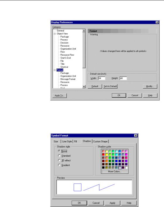
2Select the Format node in the Category tree view to display the corresponding page.
3Click the Modify button to display the Symbol Format dialog box.
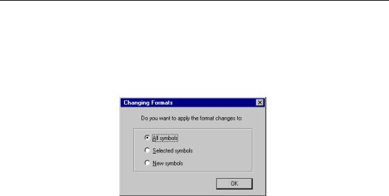
4Click the Shadow tab to display the corresponding page.
5Select a shadow style in the Shadow Style groupbox.
6Select a shadow color from the color palette.
0RGHO GLVSOD\ SUHIHUHQFHV
7Click OK.
You return to the Display Preferences dialog box.
8Click OK.
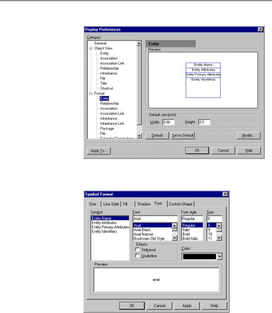
The Changing Formats window appears. In indicates symbols to which the change applies.
9Select a radio button.
10Click OK.
6HOHFWLQJ IRQW GLVSOD\ SUHIHUHQFHV
You can define the display preferences for the font, size, style, and color of text associated with symbols in the model. When you modify font preferences, they apply to all existing and new symbols.
ϖ7R PRGLI\ IRQW GLVSOD\ SUHIHUHQFHV
1Select Tools→Display Preferences to display the Display Preferences dialog box.
&KDSWHU 0RGHO *UDSKLFV
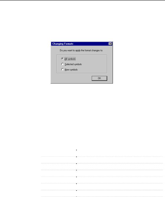
2 Select a symbol node to display the corresponding page.
3Click the Modify button to display the Symbol Format dialog box.
4Click the Font tab to display the corresponding page.
5Select the item for which you want to change font.
6Select a font.
7Select a font style, size, color, or effect in the corresponding groupboxes.
0RGHO GLVSOD\ SUHIHUHQFHV
8Click OK.
You return to the Display Preferences dialog box.
9Click OK.
The Changing Formats window appears. In indicates symbols to which the change applies.
10Select a radio button.
11Click OK.
6HOHFWLQJ WH[W DOLJQPHQW IRU IUHH V\PEROV
You can define the alignment of text in the following free symbols: rectangles, ellipses, rounded rectangles, and polygons.
For each free symbol, you can define the following text alignment parameters:
|
3DUDPHWHU |
'HVFULSWLRQ |
|
Center |
Centers the text horizontally and vertically |
|
Horizontal left |
Aligns text to the left according to a horizontal axis |
|
|
Horizontal right |
Aligns text to the right according to a horizontal axis |
|
|
Horizontal center |
Centers text according to a horizontal axis |
|
|
Vertical top |
Aligns text to the top according to a vertical axis |
|
|
Vertical bottom |
Aligns text to the bottom according to a vertical axis |
|
|
Vertical center |
Centers text according to a vertical axis |
|
|
Word wrapping |
Displays text in the space taken by the free symbol |
|
|
|
|
&KDSWHU 0RGHO *UDSKLFV
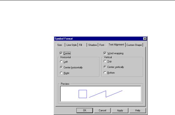
ϖ7R VHOHFW WH[W DOLJQPHQW GLVSOD\ SUHIHUHQFHV
1Right-click a free symbol and select Format from the contextual menu to display the Symbol Format dialog box.
2Click the Text Alignment tab to display the corresponding page.
3Select the Center check box.
RU
Select alignment parameters in the Horizontal and Vertical boxes.
RU
Click the Word Wrapping check box.
4Click OK.
0RGLI\LQJ V\PERO DSSHDUDQFH
0RGLI\LQJ V\PERO DSSHDUDQFH
You can modify the display of individual symbols in a model including object symbols, relationships, free symbols, and lines.
6HOHFWLQJ V\PEROV
Selecting symbols is the first step in many operations that modify the appearance of a diagram. Before you can change the appearance of symbols in a model, you must select one or more symbols.
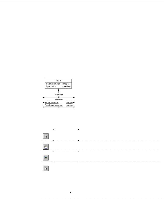
Selected symbols display handles. For example, the illustration below shows the selection of the Member table.
Selection tools |
The following selection tools are available for selecting symbols in a |
|
diagram: |
|
|
|
7RRO |
|
6HOHFWLRQ |
|
+RZ WR XVH |
|
|
|
|
|
|
One |
|
Click the Pointer tool in the tool palette, then click a |
|
|
|
|
|
symbol in the model |
|
|
|
All |
|
Click the Grabber tool to select all symbols in the |
|
|
|
|
|
|
|
|
|
diagram |
|
|
|
Symbols in an |
|
Click the Pointer tool or the Lasso tool, then outline the |
|
|
|
|
|
|
|
area |
|
area containing the symbols |
|
|
|
Symbols in |
|
Click the pointer tool, then click the first selection and |
|
|
|
|
|
|
|
different areas |
|
press the SHIFT key while you click additional symbols |
|
|
|
|
|
|
Selection menu |
The following menu choices are available for selecting symbols in a diagram: |
|
0HQX LWHP |
|
$FWLRQ |
|
|
|
|
Select All |
|
Selects all symbols in the diagram |
|
Select Connected |
|
Selects all symbols connected to one or more selected |
|
|
|
Symbols |
|
symbols in the diagram |
|
|
|
PowerDesigner |
|
|
&KDSWHU 0RGHO *UDSKLFV
ϖ7R VHOHFW DOO V\PEROV
♦Select Edit→Select All.
All symbols in the diagram are selected and are displayed with handles.
ϖ7R VHOHFW FRQQHFWHG V\PEROV
1 Select one or more connected symbols.
2Select Edit→Select Connected Symbols.
All symbols in the diagram that are connected directly to the selected symbol(s) are displayed with handles.
$SSO\LQJ FRORU WR D V\PERO
The following color options are available:
|
&RORU RSWLRQ |
$SSOLHV FRORU WR |
|
Line color |
Lines and the outlines of shapes and symbols containing text |
|
Fill color |
Interior of shapes and symbols containing text |
|
|
Fill effect |
|
|
Shadow color |
Interior of shadows of symbols and lines |
|
|
Interior of 3D effects, or gradients of symbols and lines |
|
Text color |
Text associated with symbols and free text |
|
|
|
|
$SSO\LQJ OLQH FRORU
ϖ7R DSSO\ D OLQH FRORU WR D V\PERO
1 Select one or more symbols.
2 Select Symbol→Format to display the Symbol Format dialog box. 3 Click the Line Style tab.
4 Click the Color dropdown listbox.
5 Select a color.
6 Click OK.
0RGLI\LQJ V\PERO DSSHDUDQFH
$SSO\LQJ ILOO FRORU
ϖ7R DSSO\ D ILOO FRORU WR D V\PERO
1 Select one or more symbols.
2 Select Symbol→Format to display the Symbol Format dialog box. 3 Click the Fill tab.
4 Select a color.
5 Select an effect.
6 Click OK.
$SSO\LQJ WUDQVSDUHQF\ WR IUHH V\PEROV
|
You can apply transparency to free symbols. Transparent symbols become a |
|
sort of skeleton as they take the color of the diagram background and can |
|
only be selected by clicking on their borders. |
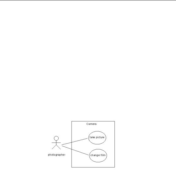
Use case system |
You can apply transparency to the rectangle you draw to represent the system |
|
in the use case diagram. |
ϖ7R DSSO\ WUDQVSDUHQF\ WR IUHH V\PEROV
1 Select one or more symbols.
2 Select Symbol→Format to display the Symbol Format dialog box. 3 Click the Fill tab.
4 Deselect the Fill color check box.
5 Click OK.
&KDSWHU 0RGHO *UDSKLFV
$SSO\LQJ VKDGRZ FRORU
ϖ7R DSSO\ D VKDGRZ FRORU WR D V\PERO
1 Select one or more symbols.
2 Select Symbol→Format to display the Symbol Format dialog box. 3 Click the Shadow tab.
4Select the Standard radio button.
RU
Select the 3D Effect radio button.
RU
Select the Gradient radio button.
5Select a color from the color palette.
6Click OK.
$SSO\LQJ WH[W FRORU
ϖ7R DSSO\ D WH[W FRORU WR D V\PERO
1 Select one or more symbols.
2 Select Symbol→Format to display the Symbol Format dialog box. 3 Click the Font tab.
4 Select a font color.
5 Click OK.
$SSO\LQJ D OLQH VW\OH WR V\PEROV
You can modify the line style of any symbol in the model. Your selection is saved in the current model and applies only to the current model. The line style applies to selected symbols. In addition, the choice of jagged, right sharp, right rounded, or waved lines applies to all new lines.
0RGLI\LQJ V\PERO DSSHDUDQFH
Line styles apply to different symbols, as follows:
6W\OHV |
$SSOLHV VW\OH WR |
|
Lines and the outlines |
|
of shapes and symbols |
|
containing text |
|
Lines and the outlines |
|
|
of shapes and symbols |
|
containing text |
|
Lines drawn with |
|
|
Line or Polyline tools |
|
only |
|
|
All lines
ϖ7R DSSO\ D OLQH VW\OH WR D V\PERO
1 Select one or more symbols.
'HVFULSWLRQ
Defines the thickness of a line
Apply invisible, solid, dashed, and dotted lines
Position arrowhead at the beginning, the center and the end of lines
Make angles jagged, right sharp, right rounded or waved
2Select Symbol→Format to display the Symbol Format dialog box.
3Click the Line Style tab.
4Click the Style dropdown listboxes.
5Select a OLQH VW\OH.
6Click OK.
&XVWRPL]LQJ WKH VKDSH RI D V\PERO
The Custom Shape page lets you define a new shape for most non-link symbols. Some predefined shapes are delivered with PowerDesigner, and you can also create your own shapes using the appropriate editor.

