

1 / zobaa_a_f_cantel_m_m_i_and_bansal_r_ed_power_quality_monitor
.pdf8
Selection of Voltage Referential from the Power Quality and Apparent Power Points of View
Helmo K. Morales Paredes1, Sigmar M. Deckmann1, Luis C. Pereira da Silva1 and Fernando P. Marafão2
1School of Electrical and Computer Engineering, University of Campinas, 2Group of Automation and Integrated Systems, Unesp – Univ Estadual Paulista Brazil
1. Introduction
When one tries to go further into the discussions and concepts related to Power Quality, one comes across basic questions about the voltage and current measurements. Such issues do not emerge only because of the evolution of sensors and digital techniques, but mainly because of the need to better understand the phenomena related with three-phase circuits under asymmetrical and/or distorted waveform conditions.
These issues are fundamental, both for establishing disturbance indicators as well as for power components formulation under non sinusoidal and/or asymmetrical waveforms. This can be verified by the various conferences that have been dedicated to this topic and the growing number of articles published about this subject (Depenbrock, 1993; Akagi et al, 1993; Ferrero, 1998; Emanuel, 2004; Czarneck, 2008; IEEE Std 1459, 2010; Tenti et al., 2010; Marafao et al., 2010).
Several discussions have shown that the choice of the voltage reference point can influence the definitions and calculation of different power terms and power factor (Emmanuel, 2003; Willems & Ghijselen, 2003; Willems, 2004; Willems et al., 2005). Consequently, it may influence applications such as revenue metering, power conditioning and power systems design. Taking into account two of the most relevant approaches (Depenbrock, 1993; IEEE Std 1459, 2010), regarding to, e.g., the power factor calculation, it can be seen that quantitative differences are practically irrelevant under normal operating conditions, as discussed and demonstrated in (Moreira et al., 2006). However, under severe voltage and current deterioration, particularly in case of power circuits with a return conductor, the differences may result significant.
Nevertheless, the matter of voltage referential is much more extensive than the definitions or calculations of power terms and it can have a direct effect on many other power system’s applications, such as: power quality instrumentation and analysis, protection, power conditioning, etc.
Thus, this chapter deals with the selection of the very basic voltage referential and its influence of the quantification of some power quality indicators, as well as, in terms the apparent power definition.
The analysis of some power quality indices will illustrate how the selection of the voltages referential may influence the evaluation of, e.g., the total harmonic distortion, unbalance

138 |
Power Quality – Monitoring, Analysis and Enhancement |
factors and voltage sags and swells, especially in case of three-phase four-wire circuits. Such case deserves special attention, both, from instrumentation and regulation points of view. Finally, based on the classical Blakesley’s Theorem, a possible methodology will be presented in order to allow the association of the most common voltage measurement approaches, in such a way that the power quality (PQ) and power components definitions would not be improperly influenced.
2. Choosing the voltage referential in three phase power systems
It is not possible to discuss the choice of a circuit voltage referential, without first recalling Blondel's classic definition (Blondel, 1893), which demonstrates that in a polyphase system with “m” wires between source and load, only “m-1” wattmeters were needed to measure the total power transferred from source to load. In this case, one of the wires should be taken as the referential, be it either a phase or a return (neutral) conductor (Fig. 1).
Fig. 1. Illustration of the measuring method according to Blondel
This hypothesis was extended to various other power system applications and it is also currently used, as can be seen, for example, in (IEEE Std 1459, 2010). However, other proposals have also been discussed, such as the utilization of a referential external to the power circuit (Depenbrock, 1993; Willems & Ghijselen, 2003; Blondel, 1893; Marafão, 2004).
2.1 External voltage referential
In this case, all wires, including the neutral (return), should be measured to a common point outside the circuit (floating), as shown in Fig. 2. This common point was designated by Depenbrock as a virtual reference or a virtual star point (*). In the same way as Blondel’s work, the author originally dealt with the problem of choosing the voltage referential from the point of view of power transfer.
In practice, this method requires that an external point (*) be used as the voltage referential. This point can be obtained connecting “m” equal resistances (or sensor’s impedances) among each wire on which the voltage should be measured. Voltage drops over these resistors correspond to the voltages that characterize the electromagnetic forces involved. Depenbrock has demonstrated that such measured voltages always sum up to zero, according to Kirchhoff's Voltage Law (Depenbrock, 1998).
Therefore this method is applicable to any number of wires, independently of the type of connection (Y-n, Y ou ). It must be emphasized that measured voltages in relation to the virtual point can be interpreted as virtual phase voltages, although they do not necessarily equal the voltages over each branch of a load connected in Y-n, Y or , especially when they

Selection of Voltage Referential from the Power Quality and Apparent Power Points of View |
139 |
are unbalanced. Thus, the use of voltages in relation to the virtual point needs to be treated in a special way so as to arrive at phase or line quantities, as will be shown further on.
|
|
|
|
|
|
|
|
|
|
|
|
|
|
|
|
|
|
|
|
|
|
|
|
|
|
|
|
|
|
|
|
|
|
|
|
|
|
|
|
|
|
|
|
|
|
|
|
|
|
|
|
|
|
|
|
|
|
|
|
|
|
|
|
|
|
|
|
|
|
|
|
|
|
|
|
|
|
|
|
|
|
|
|
|
|
|
|
|
|
|
|
|
|
|
|
|
|
|
|
|
|
|
|
|
|
|
|
|
|
|
|
|
|
|
|
|
|
|
|
|
|
|
|
|
|
|
|
|
|
|
|
|
|
|
|
|
|
|
|
|
|
|
|
|
|
|
|
|
|
|
|
|
|
|
|
|
|
|
|
|
|
|
|
|
|
|
|
|
|
|
|
|
|
|
|
|
|
|
|
|
|
|
|
|
|
|
|
|
+ + = 0 |
|
|
|
|
|
|
+ + |
|
|
|
|||||||
|
|
|
|
|
|
|
|
|
|
|
|
|
||||||||||
|
|
|
|
|
a) 3+ + = 0 |
+ + |
+ = 0 |
|
||||||||||||||
|
|
|
|
|
|
|
wire circuit |
|
|
|
|
|
|
|
b) 4 wire circuit |
|
||||||
Fig. 2. Voltages measurement considering a virtual star point (*)
2.2 Internal voltage referential
Based on Blondel’s proposals, recent discussions and recommendations made by Standard 1459 (IEEE Std 1459, 2010) suggest that voltage should be measured in relation to one of the system’s wires, resulting in phase to phase voltages (line voltage) or phase to neutral voltages, according to the topology of the system used. In this approach, the number of voltage sensors is smaller than in the case of measurements in relation to a virtual point. Fig. 3 shows a measuring proposal considering one of the system’s conductor as the reference.
va Za
|
|
ia |
|
L |
vb |
Zb |
|
vab |
|
|
O |
|||
|
|
|
||
vc |
Zc |
|
vbc |
A |
|
D |
|||
|
|
|
||
|
|
ic |
|
|
+= −
+= −
a)3 wire circuit
va |
Za |
a |
|
|
|
|
|||
|
ia |
|
L |
|
vb |
Zb |
|
||
b |
O |
|||
|
ib |
|||
|
|
A |
||
vc |
Zc |
|
||
c |
D |
|||
|
||||
|
ic |
van vbn vcn |
|
|
|
Zn |
|
||
|
+ + |
n |
|
|
|
= 3 |
|
||
|
+b) 4+wire= 3 |
= − |
|
|
|
circuit |
|
||
Fig. 3. Voltage measurement considering an internal referential
Note that, in case of 4 wire the phase voltages and currents may not sum zero. Where and are the zero sequence voltage and current components.
3. Considerations on three phase power system without return conductor
In this circuit topology, the lack of a return conductor allows either the selection of a virtual reference point (Fig. 2a) or a phase conductor reference (Fig. 3a). Apart from the fact that there is no zero-sequence current circulation, in the three-phase three-wire connection
140 |
Power Quality – Monitoring, Analysis and Enhancement |
(system without a return wire), the zero-sequence voltage is also eliminated from the quantities measured between the phases. This is a direct consequence of Kirchhoff’s laws. Thus, considering three-wire systems and taking into account different applications, both measuring methods can have advantages and disadvantages. For example:
•With regard to low voltage applications one can conclude that the measurement of line quantities (Fig. 3a) results in the reduction of costs associated to voltage transducers;
•Assuming a common external point (Fig. 2a), the measurements need to be manipulated (adjusted) to obtain line voltages;
•However if we take into account high and medium voltage applications, measurements based on the scheme shown in Fig. 3a may not be the most adequate. Usually at these levels of voltage two methods are employed: the first requires the use of Voltage Transformers (VTs), which have a high cost, since they handle high line voltages. The second strategy, which is cheaper, is to employ capacitive dividers, which, in general, use the physical grounding of the electric system as a measuring reference. The problem is that this type of grounding is the natural circulation path for transient currents, leakage currents, atmospheric discharges, etc. resulting in a system with low protection levels for the measuring equipment;
•Therefore, when considering the previous case (high and medium voltage), the use of a virtual reference point may be a good strategy, since it would guarantee that the equipment is not subjected to disturbances associated to the grounding system. However, this connection with a floating reference point could cause safety problems to the instrument operator, since during transients the voltage of the common point could fluctuate and reach high values in relation to the real earth (operator).
4. Considerations on three phase power system with return conductor
The presence of the return conductor allows the existence of zero-sequence fundamental or harmonic components (homopolars: and ), and in this case, it is extremely important that these components are taken into account during the power quality analyses or even in the calculation of related power terms.
According to Fig. 3b, the reference in the return wire allows the detection of zero-sequence voltage ( ) by adding up the phase voltages. According to Fig. 2b, the detection of possible homopolar components would be done directly through the fourth transducer to the virtual point ( ), which represents a common floating point, of which the absolute potential is irrelevant, since only voltage differences are imposed on the three-phase system. In the same way as for three-wire systems, there are some points that should to be discussed in case of four-wire systems:
•Considering the costs associated to transducers, it is clear that the topology suggested in Fig. 3b would be more adequate because of the reduction of one voltage sensor.
•On the other hand, many references propose the measurement of phase voltage (a,b,c,) and also of the neutral (n). The problem in this case is that it is not always clear which is the voltage reference and which is the information contained in such neutral voltage measurements. Usually phase voltages are considered in relation to the neutral wire and neutral voltage is measured in relation to earth or a common floating point (*). This cannot provide the same results. In order to attend the Kirchhoff’s Law, the sum of the measured voltages must be zero, which can only happen when voltages are measured in relation to the same potential.

Selection of Voltage Referential from the Power Quality and Apparent Power Points of View |
141 |
•Comparing the equations related to Figs. 2b and 3b, we would still ask: what is the
relationship between |
e |
|
, since the voltages measured in relation to the virtual |
those measured in relation to the neutral conductor? Therefore, |
|||
point are different from |
|
3 |
|
taking into account these two topologies, it is essential the discussion about the impact of the voltage’s referential on the assessment of homopolar components (zerosequence), as well as on the RMS value calculation or during short-duration voltage variations. As will be shown, the measured voltages in relation to an external point has its homopolar components (fundamental or harmonic) attenuated by a factor of 1/m (m
=number of wires), which has direct impact on the several power quality indicators.
5.Apparent power definitions using different voltage referential
To analyze the influence of the voltage referential for apparent power and power factor calculations, two different apparent power proposals have been considered: the FBD Theory and the IEEE Std 1459. The following sections bring a briefly overview of such proposals.
5.1 Fryze-Buchholz-Depenbrock power theory (FBD-Theory)
The FBD-Theory collects the contribution of three authors (Fryze, 1932; Buchholz, 1950, Depenbrock, 1993) and it was proposed by Prof. Depenbrock (Depenbrock, 1962, 1979), who extended the Fryze’s concepts of active and non active power and current terms to polyphase systems. At the same time, Depenbrock exploited some of the definitions of apparent power and collective quantities which were originally elaborated by Buchholz.
The FBD-Theory can be applied in any multiphase power circuit, which can be represented by an uniform circuit on which none of the conductors is treated as an especial conductor. In this uniform circuit, the voltages in the m-terminals are referred to a virtual star point “*”. The single requirement is that Kirchhoff’s laws must be valid for the voltages and currents at the terminals (Depenbrock, 1998).
Considering the three-phase four-wire systems (Fig. 2b), the collective instantaneous voltage and current have been defined as:
Σ( ) = |
+ |
+ |
+ |
|
(1) |
Σ( ) = |
+ |
+ |
+ |
|
|
Thus leading straight to the collective RMS voltage and current
Σ = |
+ |
+ |
+ |
(2) |
Σ = |
+ |
+ |
+ |
|
Differently from conventional definitions of apparent power, the Collective Apparent Power has been defined as:
Σ = Σ Σ = |
+ |
+ + |
+ + + |
(3) |
|

142 |
Power Quality – Monitoring, Analysis and Enhancement |
Considering the existing asymmetries in real three-phase systems and the high current level which can circulate through the return conductor (when it is available), this definition also takes into account the losses in this path, which is not common in many other definitions of apparent power. According to various authors, this definition is the most rigorously presented up to that time, since it takes into account all the power phenomena which take place in relation to currents and voltages in the electric system (losses, energy transfer, oscillations, etc.).
The (collective) active power was given by:
|
Σ = |
1 |
( |
|
+ |
|
+ |
|
+ |
|
) |
|
(4) |
||
For three-wire systems (Fig. 2a) |
= 0 and |
= 0 the expressions (3) and (4) become: |
|
||||||||||||
|
Σ = Σ Σ = |
|
+ |
|
+ |
|
|
|
+ |
+ |
|
(5) |
|||
and |
|
|
|
|
|
||||||||||
|
Σ = |
1 |
( |
|
+ |
|
+ |
|
) |
|
|
(6) |
|||
The collective active power has the same meaning and becomes identical to the conventional active (average) power ( ), for both threeor four-wire systems, as indicated in (4) and (6). Finally the collective power factor has been defined as:
Σ = |
Σ |
(7) |
Σ |
And it represents the overall behavior (or efficiency) of the polyphase power circuit.
5.2 IEEE Standard 1459
One of the main contributions of STD 1459 is the recommendation of the use of "equivalent" voltage and current for three-phase threeand four-wire systems (Emanuel, 2004; IEEE Std 1459, 2010). These values are based on a model of a balanced equivalent electric system, which should have exactly the same losses and/or use of power as the real unbalanced system (Emanuel, 2004; IEEE Std 1459, 2010 ).
Considering a three-phase four-wire system, the STD 1459 recommends using the values of the equivalent or effective voltage and current as:
= |
3( + |
+ ) + + + |
|
18 |
(8)
++ +
=3
The voltage and current equivalent variables were initially defined by Buchholz and Goodhue (Emmanuel, 1998) in a similar formula and as an alternative way by Depenbrock

Selection of Voltage Referential from the Power Quality and Apparent Power Points of View |
143 |
(2). Note that the effective current depends on all line and return currents and the effective voltage represents an equivalent phase voltage, which is based on all phase-to-neutral and line voltages.
Thus, the Effective Apparent Power has been defined as:
= 3 = 3 |
3( + |
+ ) + + + |
+ + + |
(9) |
|
18 |
3 |
|
This effective apparent power represents the maximum active power which can be transmitted through the three-phase system, for a balanced three-phase load, supplied by an effective voltage ( ), keeping the losses constant in the line.
And the active power is:
For three-wire |
systems |
= |
1 |
( |
|
+ |
|
|
+ |
) |
|
|
|
(10) |
||
|
. Then, |
considering only the line voltages |
the STD 1459 |
|||||||||||||
|
|
equation for the effective apparent power: |
|
|||||||||||||
suggests using the following= 0 |
+ |
|
+ |
|
|
+ |
|
+ |
|
|
||||||
and |
= 3 |
= 3 |
|
9 |
|
|
3 |
|
(11) |
|||||||
|
|
= |
1 |
( |
|
|
+ |
|
) |
|
|
|
|
(12) |
||
Consequently, the Effective Power Factor has been defined as:
= |
|
(13) |
|
Equation (13) represents the relationship between the real power to a maximum power which could be transmitted whilst keeping constant the power losses in the line. In the same way as in (7), the effective power factor indicates the efficiency of the overall polyphase power circuit.
5.3 Comparison between the FBD and IEEE STD 1459 power concepts
Accordingly to the previous equations and based on the Blondel theorem (Blondel, 1893), it is possible to conclude that the active power definitions from FBD or STD do not depend on the voltage referential, which could be arbitrary at this point. It means that:
Σ = |
1 |
( + + + ) = |
1 |
( |
+ |
+ |
) = |
(14) |
Considering the analyses of the collective and effective currents and voltages by means of symmetrical components, the following relations could be extracted from (Willems et al. 2005):

144 |
|
|
|
|
Power Quality – Monitoring, Analysis and Enhancement |
||
|
|
|
|
|
|
(15) |
|
= √3 |
= ( ) |
+ ( ) +4( ) |
|||||
|
|||||||
where the positive sequence, negative sequence and zero-sequence components are indicated by the subscripts + , - and 0, respectively.
Moreover, in case of unbalanced three phase sinusoidal situation, the collective RMS values of the voltage (FBD) can also be expressed by means of the sequence components, such as:
= ( ) + ( ) |
+ |
1 |
( |
) |
(16) |
4 |
|
Now, assuming the equivalent voltage from the STD:
= ( ) +( ) |
+ |
1 |
( |
) |
(17) |
2 |
|
It is possible to observe that the equivalent and collective currents match for both proposals, except for the factor √3 , which indicates the difference between the single and three-phase equivalent models of the STD and FBD, respectively. However, from (16) and (17) one can notice that the equivalent voltages differ for these two proposals.
Consequently, the choice of the voltage referential affects the zero-sequence components calculation and therefore, it affects the effective and collective voltages definitions, as well as the apparent power and power factor calculations in both analyzed proposals.
Next sections will illustrate the influence of the voltage referential in terms of several power quality indicators.
6. The influence of the voltage referential on power quality analyses
In this section, several simulations will be presented and discussed considering three-phase threeand four-wire systems. The main goal is to focus on the effect of different voltage referentials (return conductor or virtual star point) on the analyses of some Power Quality (PQ) Indicators. The resulting voltage measurements and PQ indicators using both voltage referentials will be also compared to the voltages at the load terminals. The main disturbances considered in the analysis are: harmonic distortions, voltage unbalances and voltage sag.
The analyses of such disturbance can be exploited in terms of the following indicators:
•RMS value:
= |
1 |
( ) |
(18) |
•Total Harmonic Distortion (THDV):
= |
∑ |
(19) |

Selection of Voltage Referential from the Power Quality and Apparent Power Points of View |
145 |
•Voltage Unbalance Factors:
=
(20)
=
In the first case, events in the voltage source are generated to quantify the impact of the voltage reference on the occurrence of voltage sags. In the second case, distortions are generated in the voltage source by injecting odd harmonics up to the fifth order with amplitudes of 50% of the fundamental. In the third case, imbalances are imposed through the voltage source, generating negativeand zero-sequence components.
6.1 Three phase power system without return conductor
Considering the line quantities estimation (load in delta configuration) and assuming the voltage measurements referred to a virtual point, an adaptation of the algorithm is necessary since these voltages are virtual phase voltages, and the line voltages can be expressed as:
|
− |
|
= |
|
|
|
|
|
− |
|
= |
|
(21) |
and the RMS values are: |
− |
|
= |
|
|
|
|
= |
1 |
( |
− |
) |
|
|
= |
1 |
( |
− |
) |
(22) |
|
= |
1 |
( |
− |
) |
|
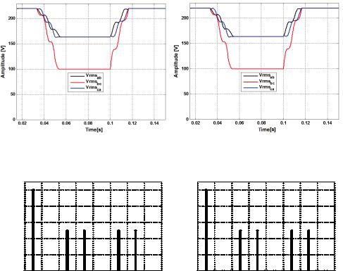
In the case of an under-voltage event, Fig. 4 shows that both measuring methods adequately represent the impact effectively experienced by load (superimposed curves), either in terms of their magnitude or duration of the voltage sag. On the other hand, Fig. 5 shows that both measuring topologies being discussed are equivalent with regard to the measuring of harmonic components, thus representing their impact on the loads (superimposed spectra).
To assess the performance of both methodologies with regard to the unbalance factors, the three-phase source was defined with amplitude and phase angle as indicated in Table 1.
146 |
Power Quality – Monitoring, Analysis and Enhancement |
b) Reference at phase b |
b) Reference at the virtual point |
Fig. 4. Evolution RMS values during voltage sag between phases b and c from 220V to 100V (4 cycles).
Mag (% of Fundamental)
100 |
|
|
|
|
|
|
|
|
80 |
|
|
|
|
|
|
|
|
60 |
|
|
|
|
|
|
|
|
40 |
|
|
|
|
|
|
|
|
20 |
|
|
|
|
|
|
|
|
00 |
2 |
4 |
6 |
8 |
10 |
12 |
14 |
16 |
|
|
|
Harmonic order |
|
|
|
||
b) Reference at phase b
Mag (% of Fundamental)
100 |
|
|
|
|
|
|
|
|
80 |
|
|
|
|
|
|
|
|
60 |
|
|
|
|
|
|
|
|
40 |
|
|
|
|
|
|
|
|
20 |
|
|
|
|
|
|
|
|
00 |
2 |
4 |
6 |
8 |
10 |
12 |
14 |
16 |
|
|
|
Harmonic order |
|
|
|
||
b) Reference at the virtual point
Fig. 5. Spectral analysis with each measuring topology (3 wires)
|
Test 1 |
|
Test 2 |
||
Source Voltage |
Amplitude |
Angle |
Amplitude |
|
Angle |
va |
179.61 V |
0o |
179.61 V |
|
0o |
vb |
159.81 V |
-104.4o |
159.81 V |
|
-104.4o |
vc |
208.59 V |
132.1o |
208.59 V |
|
144o |
|
Test 3 |
|
Test 4 |
||
|
Amplitude |
Angle |
Amplitude |
|
Angle |
va |
197.57 V |
0o |
197.57 V |
|
0o |
vb |
171.34 V |
-125.21o |
171.34 V |
|
-114.79o |
vc |
171.34 V |
125.21o |
171.34 V |
|
114.79o |
Table 1. Voltages and phase angles programmed at the power source
In this case the negative-sequence unbalance factor (K-) is identical for both measuring methodologies (vide table 2), which also coincides with the theoretical value and the