

1 / zobaa_a_f_cantel_m_m_i_and_bansal_r_ed_power_quality_monitor
.pdfPart 2
Power Quality Enhancement and
Reactive Power Compensation and
Voltage Sag Mitigation of Disturbances
11
Active Load Balancing in a Three-Phase Network by Reactive Power Compensation
Adrian Pană
“Politehnica” University of Timisoara
Romania
1. Introduction
1.1 Brief overview of the causes, effects and methods to reduce voltage unbalances
in three-phase networks
During normal operating condition, a first cause of voltage unbalance in three-phase networks comes from the asymmetrical structure of network elements (electrical lines, transformers etc.). Best known example is the asymmetrical structure of an overhead line, as a result of asymmetrical spatial positioning of the conductors. Also the total length of the conductors on the phases of a network may be different. This asymmetry of the network element is reflected in the asymmetry of the phase equivalent impedances (self and mutual, longitudinal and transversal). The impedance asymmetry causes then different voltage drop on the phases and therefore the voltage unbalance in the network nodes. As an example of correction method for this asymmetry is the well-known method of transposition of conductors for an overhead electrical line, which allows reducing the voltage unbalance under the admissible level, of course, with the condition of a balanced load transfer on the phases.
But the main reason of the voltage unbalance is the loads supply, many of which are unbalanced, single-phase - connected between two phases or between one phase and neutral. Many unbalanced loads, having small power values (a few tens of watts up to 5-10 kW), are connected to low voltage networks. But the most important unbalance is produced by high power single-phase industrial loads, with the order MW power unit, that are connected to high or medium voltage electrical networks, such as welding equipment, induction furnaces, electric rail traction etc. Current and voltage unbalances caused by these loads are most often accompanied by other forms of disturbance: harmonics, voltage sags, voltage fluctuations etc. (Czarnecki, 1995).
Current unbalance, which can be associated with negative and zero sequence components flow, lead to increased longitudinal losses of active power and energy in electrical networks, and therefore lower efficiency.
Voltage unbalance causes first negative effects on the rotating electrical machines. It is associated with increased heating additional losses in the windings, whose size depends on amount of negative sequence voltage component. It also produces parasitic couples, which is manifested by harmful vibrations. Both effects can reduce the useful life of electrical machines and therefore significant material damage.
Transformers, capacitor banks, some protection systems (e.g. distance protection), threephase converters (three-phase rectifiers, AC-DC converters) etc. are also affected by a threephase unbalanced system supply voltages.
220 |
Power Quality – Monitoring, Analysis and Enhancement |
Regarding limiting voltage unbalances, as they primarily due to unbalanced loads, the main methods and means used are aimed at preventing respectively limiting the load unbalances. From the measures intended to prevent load unbalances, are those who realize a natural balance. It may mention here two main methods:
•balanced repartition of single-phase loads between the phases of the three-phase network. This is particularly the case of single-phase loads supplied at low voltage;
•connecting unbalanced loads to a higher voltage level, which generally corresponds to the solution of short-circuit power level increasing at their terminals. Is the case of
industrial loads, high power (several MVA or tens of MVA) to which power is supplied by its own transformer, other than those of other loads supplied at the same node. Under these conditions the voltage unbalance factor will decrease proportionally with increasing the short-circuit power level.
From the category of measures to limit unbalanced conditions are:
•balancing circuits with single-phase transformers (Scott and V circuit) (UIE, 1998);
•balancing circuits through reactive power compensation (Steinmetz circuit), single and three phase, which may be applied in the form of dynamic compensators type SVC (Static Var Compensator) (Gyugyi et al., 1980; Gueth et al., 1987; San et al., 1993; Czarnecki et al., 1994; Mayordomo et al., 2002; Grünbaum et al., 2003; Said et al., 2009).
•high performance power systems controllers - based on self-commutated converters
technology (e.g. type STATCOM - Static Compensator) (Dixon, 2005).
This chapter is basically a theoretical development of the mathematical model associated to the circuit proposed by Charles Proteus Steinmetz, which is founded now in major industrial applications.
2. Load balancing mechanism in the Steinmetz circuit
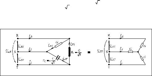
As is known, Steinmetz showed that the voltage unbalance caused by unbalanced currents produced in a three-phase network by connecting a resistive load (with the equivalent conductance G) between two phases, can be eliminated by installing two reactive loads, an inductance (a coil, having equivalent susceptance BL = G / 3 ) and a capacitance (a capacitor with equivalent susceptance BC = −G / 3 ). The ensemble of the three receivers, forming a delta connection ( ), can be equalized to a perfectly balanced three-phase loads, in star connection (Y), having on each branch an equivalent admittance purely resistive (conductance) with the value G (Fig. 1).
a) |
b) |
Fig. 1. Steinmetz montage and its equivalence with a load balanced, purely resistive
Active Load Balancing in a Three-Phase Network by Reactive Power Compensation |
221 |
To explain how to achieve balancing by reactive power compensation of a three-phase network supplying a resistive load, it will consider successively the three receivers, supplied individually. For each receiver will determine the phase currents, which are then decomposed by reference to the corresponding phase to neutral voltages, to find active and reactive components of currents, which are used then to determine the active and reactive powers flow on the phases of the network. It is assumed that the phase-to-neutral voltages and phase-to-phase voltages at source forms perfectly symmetrical three-phase sets. Also conductor’s impedances are neglected.
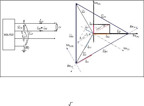
Therefore, for the case of supplying the resistive load having equivalent conductance G between R and S phases (Fig. 2.), a current in phase with the applied voltage is formed on the R phase conductor:
a) |
b) |
Fig. 2. Resistive load supplied between R and S phases
IRS = URS G |
(1) |
The equation to calculate the rms value is:
IRS = 3 U G , |
(2) |
where U is the rms value of phase-to-neutral voltage, considered the same on the three phases.
On the S phase conductor, an equal but opposite current like the one on the R phase is formed:
ISR = −IRS |
(3) |
The two currents are now reported each to the corresponding phase-to-neutral voltage, in order to find the active respectively reactive components of each other. For this, the complex plane is associated to the phase-to-neutral voltage; its phasor is positioned in the real axis,
222 Power Quality – Monitoring, Analysis and Enhancement
positive direction. It is noted that the current phasor on the phase R, IR(R)
the corresponding phase-to-neutral voltage phasor, UR , with an phase-shift equal to π /6 rad, which means that the reactive component has capacitive character:
IR(R) = IR1(R)a + jIR1(R)r = IR1(R) cos |
π |
+ jIR1(R) sin |
π |
= |
3 |
U G + j |
3 |
U G |
(4) |
|
6 |
6 |
2 |
2 |
|||||||
|
|
|
|
|
|
It can now deduce the equations for the active and reactive power flow on R phase:
SR1 = PR1 + jQR1 = UR I*R1(R) = |
3 |
U2 |
G − j |
3 |
U2 G |
(5) |
|
2 |
2 |
||||||
|
|
|
|
|
On the S phase, the current phasor is lagging the voltage US with a phase-shift equal to π /6 rad, which means that the reactive component has inductive character. By a similar calculation with the above, active and reactive powers flow on the S phase are obtained:
SS1 = PS1 + jQS1 = US IS* 1(S) = |
3 |
U2 |
G + j |
3 |
U2 G |
(6) |
|
2 |
2 |
||||||
|
|
|
|
|
It may be noted that the resistive load supplied between two phases, absorbs active power equal on the two phases. But it occurs also on the reactive power flow on the network phases, absorbing reactive power on the S phase, but returning it to the source on the R phase, without modifying the reactive power flow on all three phases.
On this ensemble, result:
P1 = PR1 + PS1 = 3 U2 G = ( 3 U)2 G şi Q1 = QR1 + QS1 = 0 |
(7) |
A similar demonstration can be done for supplying the capacitive load having the equivalent susceptance BC = −G / 3 , between phases S and T (Fig. 3).
The current formed on the S phase conductor is leading the voltage with a phase-shift equal to π /2 rad (the complex plane associated to the phase-to-phase voltageUST ):
IST = j UST |
|
BC |
|
(8) |
|
|
The rms value can be determined by the equation:
IST = 3 U |
|
BC |
|
= U G |
(9) |
|
|
The current formed on the T phase, have the same rms value and is opposite to that on the S phase:
ITS = −IST |
(10) |
Now reporting the two currents to the corresponding phase-to-neutral voltages, it can be determined the active and reactive components of this, and then the active and reactive powers on the two phases:
SS2 |
= PS2 + jQS2 |
= US IS* 2(S) = − |
1 |
U2 |
G − j |
3 |
U2 G |
(11) |
|
2 |
2 |
||||||||
|
|
|
|
|
|
|
Active Load Balancing in a Three-Phase Network by Reactive Power Compensation |
223 |
|||||||
ST 2 = PT 2 + jQT 2 |
= UT IT* 2(S) = |
1 |
U2 |
G − j |
3 |
U2 G |
(12) |
|
2 |
2 |
|||||||
|
|
|
|
|
|
|||
It is noted that the capacitive load absorbs the same reactive power on the two phases at which it is connected. It occurs also on the active powers flow, absorbs active power on phase T, but returns it to the source on the phase S. On all three phases of the network, results:
P2 = PS2 + PT 2 = 0 |
şi |
Q2 |
= QS2 + QT 2 |
= −( |
3 U)2 BC = − |
3 U2 G |
(13) |
a) |
|
|
|
|
|
|
|
|
|
|
|
|
b) |
|
|
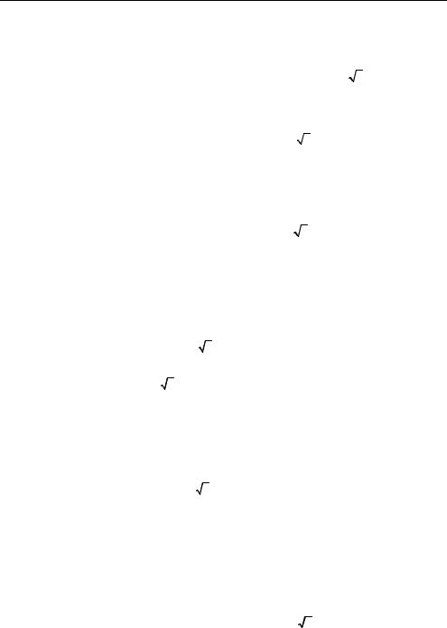
Fig. 3. The capacitive load supplied between phases S and T
The same method applies now to the case of inductive load, having equivalent susceptance BL = G / 3 supplied between T and R phases (Fig. 4).
The current formed on the T phase conductor is lagging the supplying voltage with an phase-shift equal to π /2 rad:
ITR = − j UTR BL |
(14) |
The rms value can be determined using the equation:
ITR = 3 U BL = U G |
(15) |
The current formed on the R phase, have the same rms value and is opposite to that on the T phase:
IRT = −ITR |
(16) |

224 |
Power Quality – Monitoring, Analysis and Enhancement |
a) |
b) |
Fig. 4. Inductive load supplied between T and R phases
Now reporting the two currents to the corresponding phase-to-neutral voltages, it can be determined the active and reactive components of this, and then the active and reactive powers on the two phases:
ST 3 = PT |
3 + jQT 3 = UT IT* 3(T ) = |
1 |
U2 G + j |
|
3 |
U2 G |
(17) |
|||||
2 |
|
2 |
||||||||||
|
|
|
|
|
|
|
|
|
|
|||
SS3 = PS3 |
+ jQS3 |
= UT I*R3(R) = − |
1 |
U2 |
G + j |
3 |
U2 G |
(18) |
||||
|
2 |
|
||||||||||
|
|
|
2 |
|
|
|
|
|
|
|||
It is noted that the inductive load absorbs the same reactive power on the two phases at which it is connected. It occurs also on the active powers flow, absorbs active power on phase T, but returns it to the source on the phase R. On all three phases of the network, results:
P3 = PT 3 + PR3 = 0 and Q3 = QT 3 + QR3 = ( 3 U)2 BL = 3 U2 G |
(19) |
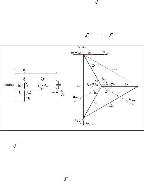
To deduce the power flow on the network phases that supply simultaneously the three loads previously considered, we can apply the superposition theorem (Fig. 5). Active and reactive powers flow run on the network phases that supply the ensemble of all three loads are obtained by algebraic addition of active and reactive power previously deducted for the individual supplying circuits. It obtains:
PR = PR1 + PR3 = U2 G , |
QR = QR1 + QR3 = 0 |
(20) |
PS = PS1 + PS2 = U2 G |
QS = QS1 + QS2 = 0 |
(21) |
PT = PT 2 + PT 3 = U2 G |
QT = QT 2 + QT 3 = 0 |
(22) |

Active Load Balancing in a Three-Phase Network by Reactive Power Compensation |
225 |
P = PR + PS + PT = 3 U2 G |
Q = QR + QS + QT = 0 |
(23) |
a) |
|
|
|
b) |
|
Fig. 5. The ensemble of the three loads
It notes that after the compensation, in the supplying network of the ensemble of the three receivers, only active power flows, the same on the three phases. The compensation conduces to maximize the power factor ( Q = 0 ) and to active load balancing on the three
phases:
P = 3 Pphase = 3 U2 G |
(24) |
The ensemble of the three loads, in connection can be equated with three equal active loads, single-phase, each having equivalent conductance with value G, in Y connection (Fig. 1). The three currents have the same phase-shift with the corresponding phase-to-neutral voltages and have the same rms value (Fig. 5):
IR = IS = IT = U G |
(25) |
3. Most common applications of Steinmetz circuit
Steinmetz circuit is usually applied to balance large loads, with values of order MW of power, whose contribution to the voltage unbalance in the connecting node is very high. Figure 6.a presents simplified supply circuit diagram of a three-phase network, of a singlephase induction furnace. Furnace coil is connected secondary of the single-phase transformer T. Its primary is connected between two phases of a medium voltage network. Capacitance C1 connected in parallel with the load, is to compensate its reactive component and therefore to improve the power factor. Capacitance C2 and inductance L2 are sized to achieve load balancing active component, as shown above. But the active power of the load is variable, depending on the specific technological process. To ensure adaptive single-phase load balancing, capacitor banks having the capacitances C1 and C2 and inductance L2 have to allow the control of these values according to load variation.

226 |
Power Quality – Monitoring, Analysis and Enhancement |
a) |
b) |
Fig. 6. Simplified circuit of Steinmetz installation for load-balancing applications in the case: a) induction furnace; b) railway electric traction
Another important application of the Steinmetz circuit is load balancing in three-phase networks which supplies electric traction railway, equivalent to a single-phase load. Figure 6.b shows the simplified circuit diagram of a substation supply of section from an electric railway line. Since the load is changing rapidly and within large limits, the compensator elements must satisfy the same requirements. Is needed a dynamic load balancing (Grünbaum et al., 2003). The solution applied use a SVC (Static Var Compensator) realized by a TCR (Thyristor Controlled Reactor). Controlling the thyristors (connected back-to-back) which are in series with the inductances L1, L2 and L3 allow a dynamic control of inductive and capacitive currents on the branches of the compensator. Thus is performed a dynamic compensation of reactive load (increasing the power factor) and dynamic balancing of active load in the supply network.
Application of the Steinmetz circuit is a simple solution, relatively inexpensive and efficient, which can be applied to any voltage level at any value of load power, a perfect load balancing on the three phases is obtained. However, it presents the following inconveniences:
-the frequency of 50 Hz, the ensemble load - compensator can be equated with impedance perfectly balanced, but on other frequencies, namely the higher harmonics that can be generated by the same load or close loads, it causes a strong unbalance;
-dimensioning the compensator should be made taking into account the restriction to avoid parallel resonance between the equivalent capacitance of the compensator and the network equivalent inductance seen at the point of connection to the network, for harmonic frequencies present in the steady operation conditions, the capacitors will be included in passive filters for harmonic currents.
4. The generalized Steinmetz circuit
The circuit available for a single phase active load connected between two phases can be extended to a certain unbalanced three-phase load with active and reactive components (inductive and / or capacitive). The mathematical model for sizing the compensator elements and determining the currents flow and powers flow for the purpose of understanding the compensation mechanism and for conception of control algorithms