

1 / zobaa_a_f_cantel_m_m_i_and_bansal_r_ed_power_quality_monitor
.pdfSelection of Voltage Referential from the Power Quality and Apparent Power Points of View |
147 |
measurements at the load terminals. As it was expected, the zero-sequence unbalance factor (K0) is nil due to the lack of a return conductor.
Test |
Theoretical Value |
Reference at |
Reference at the |
Measurement |
|||||
phase b |
virtual Point |
at load terminals |
|||||||
|
|
|
|||||||
|
K – (%) |
K 0 (%) |
K – (%) |
K 0 (%) |
K – (%) |
K 0 (%) |
K – (%) |
K 0 (%) |
|
1 |
15.92 |
0.00 |
15.92 |
0.00 |
15.92 |
0.00 |
15.92 |
0.00 |
|
2 |
19.49 |
0.00 |
19.49 |
0.00 |
19.49 |
0.00 |
19.49 |
0.00 |
|
3 |
10.00 |
0.00 |
10.00 |
0.00 |
10.00 |
0.00 |
10.00 |
0.00 |
|
4 |
0.00 |
0.00 |
0.00 |
0.00 |
0.00 |
0.00 |
0.00 |
0.00 |
|
Table 2. Unbalance factor calculated according to each measurement method
6.2 Three phase power system with return conductor
Fig. 6a shows that the voltage measurement using the return wire as the reference, correctly detects the presence of odd harmonics, with 50% amplitudes. Therefore, it is in this scenery that the real impact on the load Fig. 6 is being quantified. Note that when the virtual point is used as voltage reference (Fig. 6b) the harmonics multiples of 3 are not correctly detected. These homopolar components are attenuated by a factor of ¼ in relation to the expected voltage spectrum on the load. The other harmonic components do not suffer attenuation, because they either are of positiveor negative-sequence.
Mag (% of Fundamental)
100 |
|
|
|
|
|
|
|
|
80 |
|
|
|
|
|
|
|
|
60 |
|
|
|
|
|
|
|
|
40 |
|
|
|
|
|
|
|
|
20 |
|
|
|
|
|
|
|
|
00 |
2 |
4 |
6 |
8 |
10 |
12 |
14 |
16 |
|
|
|
Harmonic order |
|
|
|
||
Mag (% of Fundamental)
100 |
|
|
|
|
|
|
|
|
80 |
|
|
|
|
|
|
|
|
60 |
|
|
|
|
|
|
|
|
40 |
|
|
|
|
|
|
|
|
20 |
|
|
|
|
|
|
|
|
00 |
2 |
4 |
6 |
8 |
10 |
12 |
14 |
16 |
|
|
|
Harmonic order |
|
|
|
||
a) Reference at neutral conductor |
b) Reference at the virtual point |
Fig. 6. Spectrum analysis with each measuring topology (4 wires)

148 |
Power Quality – Monitoring, Analysis and Enhancement |
a) Reference at neutral conductor |
b) Reference at the virtual point |
Fig. 7. Evolution of RMS values during a voltage sag between phases b and c from 127V to 50V (4 cycles)
Fig. 7a shows when the reference is set in the return conductor the event is correctly detected and quantified (amplitude and duration) in all phases, thus representing the exact impact on the load. However with the use of a virtual point as the voltage reference the event is detected, but it does not show how it is generated or how it could affect the load (Fig. 7b). Thus, this measuring method affects the assessment of the impact during voltage sag.
According to Table 3 both the voltage reference on the return wire and on the virtual point detected equal imbalances for the negative component (K-). However, the zero-sequence indicator (K0), calculated by means of the virtual reference point voltages is different from expected. It is attenuated by a factor of ¼ (1/m).
|
Theoretical Value |
Reference at the |
Reference at the |
Measurement |
|||||
Test |
neutral conductor |
virtual point |
at load terminals |
||||||
|
|
||||||||
|
K – (%) |
K 0 (%) |
K – (%) |
K 0 (%) |
K – (%) |
K 0 (%) |
K – (%) |
K 0 (%) |
|
1 |
15.92 |
0.00 |
15.92 |
0.00 |
15.92 |
0.00 |
15.92 |
0.00 |
|
2 |
19.49 |
8.02 |
19.49 |
8.02 |
19.49 |
2.01 |
19.49 |
8.02 |
|
|
|
|
|
|
|
|
|
|
|
3 |
10.00 |
0.00 |
10.00 |
0.00 |
10.00 |
0.00 |
10.00 |
0.00 |
|
|
|
|
|
|
|
|
|
|
|
4 |
0.00 |
10.00 |
0.00 |
10.00 |
0.00 |
2.50 |
0.00 |
10.00 |
|
|
|
|
|
|
|
|
|
|
|
Table 3. Unbalance factor calculated according to each type of measurement
7. Attenuation and recovery of the zero-sequence component
From the previous results it can be concluded that in case of three-phase four wire circuits and in the presence of zero-sequence components (fundamental or harmonic), there is a clear difference between the two voltage referential methods. Therefore, it is important to provide a careful analysis of the two methodologies and the differences found between them.
Consider a set of three-phase and periodic voltage sources , e , connected as in Fig. 8. In terms of symmetric components these voltages can be expressed as:

Selection of Voltage Referential from the Power Quality and Apparent Power Points of View |
149 |
||||||||||
= |
+ |
+ |
|
|
|
|
|
||||
= |
+ |
+ |
|
|
|
|
(23) |
||||
= |
+ |
+ |
|
|
|
|
|
||||
|
|
|
|
|
|
|
|
|
|
|
|
|
|
|
|
|
|
|
|
|
|
|
|
|
|
|
|
|
|
|
|
|
|
|
|
|
|
|
|
|
|
|
|
|
|
|
|
|
|
|
|
|
|
|
|
|
|
|
|
|
|
|
|
|
|
|
|
|
|
|
|
|
|
|
|
|
|
|
|
|
|
|
|
Fig. 8. Three-phase four-wire system
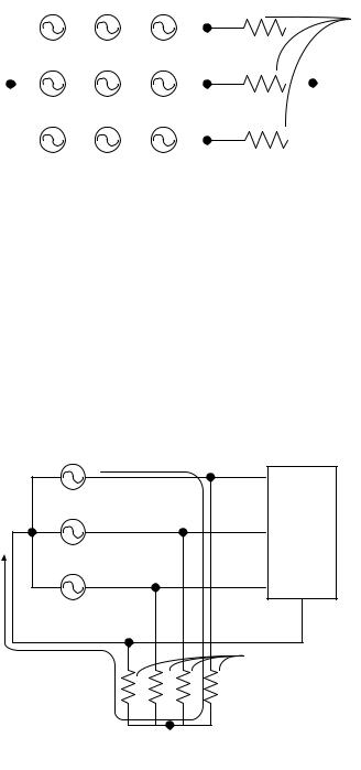
Considering the measurements with voltage reference at the neutral, Fig. 9 shows a circuit on which the neutral is utilized as the voltage reference, where R is the resistance of the voltage meter.
Fig. 9. Measurement topology considering the reference on the return conductor
Assuming that the value of is much greater than the values of the load impedances, we can take into account only the links formed by the voltage sources and the measuring instruments, and substitute the voltages of the sources by their respective sequence components. Thus, the circuit of Figure 9 can be represented as in Fig. 10.
150 |
|
|
|
|
|
|
|
Power Quality – Monitoring, Analysis and Enhancement |
||||||
|
|
|
|
|
|
|
|
|
|
|
|
|
|
|
|
|
|
|
|
|
|
|
|
|
|
|
|
|
|
|
|
|
|
|
|
|
|
|
|
|
|
|
|
|
|
|
|
|
|
|
|
|
|
|
|
|
|
|
|
|
|
|
|
|
|
|
|
|
|
|
|
|
|
|
|
|
|
|
|
|
|
|
|
|
|
|
|
|
|
|
|
|
|
|
|
|
|
|
|
|
|
|
|
|
|
|
|
|
|
|
|
|
|
|
|
|
|
|
|
|
|
|
|
|
|
|
|
|
|
|
|
|
|
|
|
|
|
|
|
|
|
|
|
|
|
|
|
|
|
|
|
|
|
|
|
|
|
|
|
|
|
|
|
|
|
|
|
|
|
|
|
|
|
|
|
|
|
|
|
Fig. 10. Equivalent circuit for measuring to the neutral conductor |
|
|||||
Since |
, |
e |
are the voltage drops over each instrument's resistances, it follows that: |
|||
|
|
|
= |
+ |
+ |
(24) |
|
|
|
= |
+ |
+ |
|
|
|
|
= |
+ |
+ |
|
In this way, it can be seen that the measured voltages in relation to the neutral correspond to the imposed voltages by the source, containing all sequence components (positive, negative and zero), as it has been shown earlier in the sag, harmonics and unbalance tests.
On the other hand, Fig. 11 shows a circuit on which the virtual point is used as the voltage referential. As in the circuit of Fig. 10, we can represent the circuit shown in Fig. 11 through its sequence components (Fig. 12).
Fig. 11. Measurement topology considering the reference on the virtual point

Selection of Voltage Referential from the Power Quality and Apparent Power Points of View |
151 |
||||||||||||||
|
|
|
|
|
|
|
|
|
|
|
|
|
|
|
|
|
|
|
|
|
|
|
|
|
|
|
|
|
|
|
|
|
|
|
|
|
|
|
|
|
|
|
|
|
|
|
|
|
|
|
|
|
|
|
|
|
|
|
|
|
|
|
|
Fig. 12. Equivalent circuit for measuring to the virtual point
As it is known, the negativeand zero-sequence components are indicators of abnormal conditions (imbalances and/or harmonics) of an electric circuit. If we consider that the negative-sequence components "see" practically the same circuit as the positive-sequence components, the return (neutral) wire therefore is not necessary, as opposed to the zerosequence current that only occurs in the presence of a return wire.
In this way, if we consider the superposition theorem, we can decompose the circuit in Fig. 12 into a circuit containing positiveand negativecomponents (Fig. 13) and another circuit containing only zero-sequence components (Fig.14).
Fig. 13. Decomposition: positiveand negative-sequence circuit by superposition theorem

152 |
|
|
|
|
Power Quality – Monitoring, Analysis and Enhancement |
||||||
|
|
|
|
|
|
|
|
|
|
|
|
|
|
|
|
|
|
|
|
|
|
|
|
|
|
|
|
|
|
|
|
|
|
|
|
|
|
|
|
|
|
|
|
|
|
|
|
Fig. 14. Decomposition: zero-sequence circuit by superposition theorem From the circuit in Fig. 13 we have the following:
± = |
+ |
|
± |
+ |
(25) |
= |
|
|
± = |
+ |
|
According to the superposition theorem (Fig.13 and 14), the measured voltages to a virtual point can be written as:
= |
± + |
|
|
= |
± + |
|
(26) |
= |
± + |
|
|
On the other hand, Fig. 14 can also be represented by the circuit shown in Fig. 15, based on Blakesley transform (Blakesley, 1894).
Thus, for the circuit in Fig. 15 we can apply the voltage divider rule:
= |
= = |
|
= |
1 |
|
||
|
4 |
(27) |
|||||
= |
|
= − |
= − |
3 |
|
|
|
|
4 |
|
|
||||

Selection of Voltage Referential from the Power Quality and Apparent Power Points of View |
153 |
|||||||||||||
|
|
|
|
|
|
|
|
|
|
|
|
|
|
|
|
|
|
|
|
|
|
|
|
|
|
|
|
|
|
|
|
|
|
|
|
|
|
|
|
|
|
|
|
|
|
|
|
|
|
|
|
|
|
|
|
|
|
|
|
Fig. 15. Transformed Zero-sequence Circuits (Blakesley's theorem)
Equation (27) indicates the zero-sequence components of phase and neutral voltages regarding to the virtual point. In this way, the total voltages (measured to the virtual point), taking into account positive-, negativeand zero-sequence components, can be obtained by substituting (27) in (26):
|
= |
+ |
+ |
1 |
|
|
|
|||
|
4 |
|
|
|
||||||
|
= |
+ |
+ |
1 |
|
|
(28) |
|||
|
4 |
|
|
|
||||||
|
= |
+ |
+ |
1 |
|
|
of its real value, which |
|||
Note that the zero sequence component is |
attenuated by a factor of |
|
||||||||
|
|
4 |
the measured value must |
|||||||
means that for applications where its quantification is necessary, |
|
¼ |
|
|||||||
be corrected. This can be done by adding (¾ |
) on both sides of the equation (29): |
|||||||||
|
+ |
3 |
|
= |
|
+ |
+ |
|
|
|
|
4 |
|
|
|
|
|
||||
|
+ |
3 |
|
= |
|
+ |
+ |
|
|
(29) |
|
4 |
|
|
|
|
|
||||
|
+ |
3 |
|
= |
|
+ |
+ |
|
|
|
From (31) we have: |
4 |
3 |
|
|
|
|
||||
|
|
|
= − |
|
|
|
|
(30) |
||
|
|
4 |
|
|
|
|
||||
154 |
Power Quality – Monitoring, Analysis and Enhancement |
Equation (30) finally provides the relationship between the measured voltage between the neutral and the virtual point and the zero-sequence component (homopolar). This equation allows us, to compare both measuring methodologies, as well as to provide algorithms for the measuring and monitoring equipments, which are correct, independently of the type of connection chosen by the end user.
Due to the differences in the apparent power, as indicated by (16) and (17), inclusion of equation (30) may be necessary in order to avoid miscalculation of the power terms and possible costumer’s penalization.
8. Conclusions
It has been shown that in case of three-phase three-wire systems (without a return wire), both voltage references (neutral or virtual point) provide identical measurements due to the lack of homopolar components (zero-sequence), which are filtered by the topology of the system itself. However for return-wire systems, there is a need to take certain aspects into consideration, as for example, the attenuation of homopolar components (zero-sequence) if measuring the voltages to a virtual star point.
In this way, to measure voltage in modern installations with the presence of distortions and imbalances, the choice of a reference point must be made very carefully and its implications must be taken into account in applications such as pricing, measurement, power quality monitoring, compensation, protection, etc.
Despite of the demonstration of how to recover the homopolar components, attenuated by the virtual point measurements, the connection referenced to the neutral continues to be the best option, especially for low voltage applications, due to the fact that it needs less one measuring channel. However, considering applications in high-voltage systems (3 wires), the use of an external virtual point may be an interesting option, from the point of view of the protection of the measuring equipments.
Finally, it is worth pointing out that the proposed methodology to associate two methods for measuring voltages, by using Blakesley Theorem, can also be used in order to find a convergence point between the different power theories.
9. Acknowledgment
The authors gratefully acknowledge the CNPq and CAPES for the Financial support.
10. References
Akagi, H. and Nabae A. (1993). The p-q Theory in Three-Phase Systems Under NonSinusoidal Conditions. ETEP European Transaction on Electrical Power Engineering. Vol. 3, No. 1, (January/February 1993), pp. 27-31.
Blakesley T. H. (1894). A New Electrical Theorem. Proceedings of the Physical Society of London, Vol.13, pp. 65-67.
Blondel A. (1893). Measurement of Energy of Polyphase currents. Proceeding of. International Electrical Congress Chicago III, pp. 112-117.
Buchholtz, F. (1950). Das Bergiffsystem Rechtleistung, Wirkleistung, totale Blindleistung. Selbstverlag München, 1950.
Selection of Voltage Referential from the Power Quality and Apparent Power Points of View |
155 |
Czarnecki, L .S. (2008). Currents’ Physical Components (CPC) Concept: A Fundamental of Power Theory. Przegląd Elektrotechniczny (Electrical Review). Vol. 84, No. 6, pp. 2837.
Depenbrock, M. (1962). Untersuchungen über die Spannungsund Leistungsverhältnisse bei Umrichtern ohne Energiespeicher. PhD Thesis, Technical University of Hannover, Germany.
Depenbrock, M. (1979). Wirkund Blindleistungen Periodischer Ströme in Ein- u. Mehrphasensystemen mit Periodischen Spannungen beliebiger Kurvenform. ETG Fachberichte No. 6, pp. 17-59.
Depenbrock, M. (1993). The FBD-Method, a Generally Applicable Tool for Analyzing Power Relations. IEEE Transaction on Power Systems. Vol.8, No.2, (May 1993), pp. 381-387, ISSN 0885-8950.
Depenbrock, M. (1998). Quantities of a MultiTerminal Circuit Determined on the Basis of Kirchhof's Laws, ETEP European Transactions on Electrical Power, Vol. 8, No. 4, pp. 249–257.
Emanuel, A. E. (1998). The Buchholz-Goodhue Apparent Power Definition: The Practical Approach For Nonsinusoidal and Unbalanced Systems. IEEE Transaction on Power Delivery, Vol. 3, pp. 344-350, ISSN: 0885-8977.
Emanuel, A. E. (2003). Reflections on the Effective Voltage Concept. Proceedings of Sixth International Workshop on Power Definitions and Measurements under Non-sinusoidal Conditions, pp. 1-8, Milano, Italy, October 13-25.
Emanuel, A. E. (2004). Summary of IEEE Standard 1459: Definitions for the Measurement of Electric Power Quantities under Sinusoidal, Nonsinusoidal, Balanced or Unbalanced Conditions. IEEE Transactions on Industry applications. Vol. 40, No. 3, (May/June 2004), pp. 869-876, ISSN: 0093-9994.
Ferrero, A. (1998). Definitions of Electrical Quantities Commonly Used in Nonsinusoidal Conditions. ETEP European Transaction on Electrical Power Engineering, Vol. 8, No. 4, (July/August 1998), pp. 235-240.
Fryze, S. (1933). Wirk-, Blindund Scheinleistung in Elektrischen Stromkreisen mit Nichtsinusförmigem Verlauf von Strom und Spannung” Elektrotechnische Zeitschrift. Vol. 53, No. 25, pp.596-599, 625-627, 700-702.
IEEE Standard 1459 (2010). IEE Standard Definitions for the Measurement of Electric Power Quantities under Sinusoidal, Non-sinusoidal, Balanced or Unbalanced Conditions. ISSN 978-0-7381-6058-0, New York USA.
Marafão F. P. (2004). Análise e Controle da Energia Elétrica Através de Técnicas de Processamento Digital de Sinais. PhD. Thesis, Universidade de Campinas (UNICAMP), Campinas, Brazil.
Marafao, F. P. Liberado, E. V. Morales Paredes, H. K. and Pereira da Silva, L. C. (2010). Three-Phase Four-Wire Circuits Interpretation by means of Different Power Theories. Proceedings of IEEE International School on Nonsinusoidal Currents and Compensation, pp. 104-109, ISBN: 978-1-4244-5436-5, Poland, June, 2010.
Moreira, A. C. Marafão, F. P. Deckmann, S. M. and Morales Paredes, H. K. (2006). Análise Comparativa das Técnicas de Medição de Potência Baseadas na Recomendação IEEE 1459-2000 e no Método FBD. Proceedings of IEEE Industry Applications Conference.
156 |
Power Quality – Monitoring, Analysis and Enhancement |
Tenti, P. Mattavelli, P. and Morales Paredes, H. K. (2010). Conservative Power Theory, Sequence Components and Accounting in Smart Grids. Przegląd Elektrotechniczny (Electrical Review). Vol. 86, No. 6, pp. 30-37, ISSN PL 0033-2097.
Willems J. L. and Ghijselen J. A. (2003). The Choice of the Voltage Reference and the Generalization of the Apparent Power. Proceedings of Sixth International Workshop on Power Definitions and Measurements under Non-sinusoidal Conditions, pp. 9-18. Milano, Italy, October 13-25.
Willems J. L. Ghijselen J. A. Emanuel A. E. (2005). The Apparent Power Concept and the IEEE Standard 1459-2000. IEEE Transaction on Power Delivery, Vol.20, No.2, pp. 876884, ISSN 0885-8977.
Willems, J. L. (2004). Reflections on Apparent Power and Power Factor in Non-sinusoidal and Poly-phase Situations. IEEE Transaction on Power Delivery. Vol 19, No.2, pp. 835-840, ISSN 0885-8977.