

1 / H03765157
.pdfIOSR Journal of Engineering (IOSRJEN) e-ISSN: 2250-3021, p-ISSN: 2278-8719 Vol. 3, Issue 7 (July. 2013), ||V6 || PP 51-57
Power Quality Improvement for Grid Connected Wind Energy System using STATCOM-Control Scheme
1Chandulal Tejavoth, 2M. Trishulapani, 3V.K.R.Mohan Rao, 4Y.Rambabu
1PG Scholar, 2,4Assistant Professor, 3Associate Professor, Holy Mary Institute of Technology & Science
Abstract: - When the wind power is connected to an electric grid affects the power quality. The effects of the power quality measurements are-the active power, reactive power, variation of voltage, flicker, harmonics, and electrical behavior of switching operations. The installation of wind turbine with the grid causes power quality problems are determined by studying this paper. For this Static Compensator (STATCOM) with a battery energy storage system (BESS) at the point of common coupling to mitigate the power quality problems. The grid connected wind energy generation system for power quality improvement by using STATCOM-control scheme is simulated using SIMULINK in power system block set. This relives the main supply source from the reactive power demand of the load and the induction generator in this proposed scheme. The improvement in power quality on the grid has been presented here according to the guidelines specified in IEC-61400 standard (International Electro-technical Commission) provides some norms and measurements.
Index terms: - International Electro-technical Commission (IEC), power quality, wind generating system (WGS), STATCOM.
I.INTRODUCTION
Centralized power generation systems are facing the twin constraints of shortage of fossil fuel and the need to reduce emissions. Long transmission lines are one of the main causes for electrical power losses. Therefore, emphasis has increased on distributed generation (DG) networks with integration of renewable energy systems into the grid, which lead to energy efficiency and reduction in emissions. With the increase of the renewable energy penetration to the grid, power quality (PQ) of the medium to low voltage power transmission system is becoming a major area of interest. Most of the integration of renewable energy systems to the grid takes place with the aid of power electronics converters [1]. The main purpose of the power electronic converters is to integrate the DG to the grid in compliance with power quality standards. However, high frequency switching of inverters can inject additional harmonics to the systems, creating major PQ problems if not implemented properly.
Custom Power Devices (CPD) like STATCOM (Shunt Active Power Filter), DVR (Series Active Power Filter) and UPQC (Combination of series and shunt Active Power Filter) are the latest development of interfacing devices between distribution supply (grid) and consumer appliances to overcome voltage/current disturbances and improve the power quality by compensating the reactive and harmonic power generated or absorbed by the load[2,3].
Solar and wind are the most promising DG sources and their penetration level to the grid is also on the rise. Although the benefits of DG includes voltage support, diversification of power sources, reduction in transmission and distribution losses and improved reliability [4], power quality problems are also of growing concern. This paper deals with a technical survey on the research and development of PQ problems related to solar and wind energy integrated to the grid and the impact of poor PQ. The probable connection topologies of CPDs into the system to overcome the PQ problems are also discussed. A custom power park concept for the future grid connection of distributed generation system is mentioned[5].
II. POWER QUALITY STANDARDS, ISSUES AND IT’S CONSEQUENCES
Power quality is the concept of powering and grounding sensitive equipment in a matter that is suitable to the operation of that equipment according to IEEE Std 1100.Various sources use the term "power quality" with different meanings. Other sources use similar but slightly different terminology like "quality of power supply" or "voltage quality”.
A. Voltage and Current Variations
Voltage and current variations are relatively small deviations of voltage or current characteristics around their nominal or ideal values. The two basic examples are voltage magnitude and frequency. On average, voltage magnitude and voltage frequency are equal to their nominal value, but they are never exactly equal.
www.iosrjen.org |
51 | P a g e |

Power Quality Improvement for Grid Connected Wind Energy System
The variation in voltage by smaller range is called voltage magnitude variation[6]. Increase and decrease of the voltage magnitude,
*Due to variation of the total load of a distribution system or part of it.
*Actions of transformer tap-changers.
*Switching of capacitor banks or reactors.
Transformer tap-changer actions and switching of capacitor banks can normally be traced back to load variations as well. Thus the voltage magnitude variations are mainly due to load variations, which follow a daily pattern. The influence of tap changers and capacitor banks makes that the daily pattern is not always present in the voltage magnitude pattern.
The different types of voltage and current variations are
*Voltage Magnitude Variation
*Voltage Frequency Variation
*Current Magnitude Variation
*Current Phase Variation
*Voltage and Current Unbalance
*Voltage Fluctuation
B. Harmonic Distortion
The complementary phenomenon of harmonic Voltage distortion is harmonic current distortion. As harmonic voltage distortion is mainly due to nonsinusoidal load currents, harmonic voltage and current distortion are strongly linked. Harmonic current distortion requires over-rating of series components like transformers and cables. As the series resistance increases with frequency, a distorted current will cause more losses than a sinusoidal current of the same rms value.
III.POWER QUALITY PROBLEMS
A. voltage interruption
A "voltage interruption" [IEEE Std.1159], "supply interruption"[EN 50160], or just "interruption" [IEEE Std.1250] is a condition in which the voltage at the supply terminals is close to zero. Close to zero is by the IEEE as "lower than 10%" [IEEE Std.1159]. Voltage interruptions are normally initiated by faults which subsequently trigger protection measures. Other causes of voltage interruption are protection operation when there is no fault present (a so-called protection maltrip), broken conductors not triggering protective measures, and operator intervention Interruptions can also be subdivided based on their duration, thus based on the way of restoring the supply:
B. Under Voltage
Under voltages of various duration are known under different names. Short-duration undervoltages are called "voltage sags" or "voltage dips." Long-duration undervoltage is simply referred to as "undervoltage. Voltage sag is a reduction in the supply voltage magnitude followed by a voltage recovery after a short period of time. When a voltage magnitude reduction of finite duration can actually be called a voltage sag[7]. For the IEEE a voltage drop is only sag if the sag voltage is between 10% and 90% of the nominal voltage. Voltage sags are mostly caused by short-circuit faults in the system and by starting of large motors.
C. Over Voltages
Just like with under voltage, overvoltage events are given different names based on their duration. Over voltages of very short duration, and high magnitude, are called "transient overvoltages," "voltage spikes," or sometimes "voltage surges." Overvoltages with a duration between about 1 cycle and 1 minute. The latter event is more correctly called "voltage swell" or "temporary power frequency overvoltage. “longer” duration overvoltages are simply referred to as "overvoltages." Long and short overvoltages originate from, among others, lightning strokes, switching operations, sudden load reduction, single-phase short-circuits, and nonlinearities[8,9]. A resonance between the nonlinear magnetizing reactance of a transformer and a capacitance (either in the form of a capacitor bank or the capacitance of an underground cable) can lead to a large overvoltage of long duration. This phenomenon is called Ferro resonance, and it can lead to serious damage to power system equipment.
D. Voltage Sag
A voltage sag is a short duration phenomenon at power system frequency resulting in a decrease in the RMS voltage magnitude from 10% to 90%. It typically lasts about half a cycle to a minute. Loads such as adjustable speed drives, process control equipment and computers are sensitive to these voltage sags. These loads may trip or misoperate even for voltage sag of 10% and lasting two cycles. Process industry applications
www.iosrjen.org |
52 | P a g e |

Power Quality Improvement for Grid Connected Wind Energy System
such as paper mills and semiconductor fabrication plants take a lot of time to restart when tripped. Since they are production oriented, the impact of the voltage sag is enormous[10-11].
E. Voltage Swell
Swell an increase to between 1.1 pu and 1.8 pu in rms voltage or current at the power frequency durations from 0.5 to 1 minute. Swells are less common than voltage sags, but also usually associated with system fault conditions. A swell can occur due to a single line to ground fault on the system, which can also result in a temporary voltage rise on the unfaulted phases. This is especially true in ungrounded or floating ground delta systems, where the sudden change in ground reference result in a voltage rise on the ungrounded phases. A swell is a period of high voltage. Swells have serious impact on equipment function; however, they are not as common as sags. Both minor and major swells affect equipment performance.
IV. TOPOLOGY FOR POWER QUALITY IMPROVEMENT
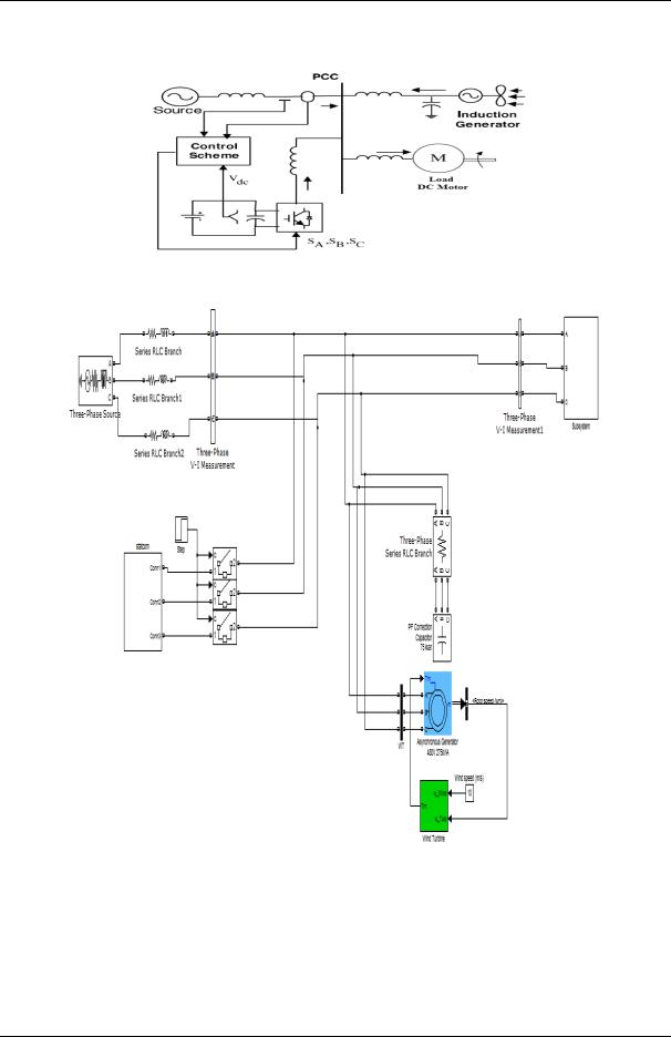
The STATCOM based current control voltage source inverter injects the current into the grid in such a way that the source current are harmonic free and their phase-angle with respect to source voltage has a desired value. The injected current will cancel out the reactive part and harmonic part of the load and induction generator current, thus it improves the power factor and the power quality. To accomplish these goals, the grid voltages are sensed and are synchronized in generating the current command for the inverter. The proposed grid connected
system is implemented for power quality improvement at point of common coupling (PCC), as shown in Fig. 1. The grid connected system in Fig. 1, consists of wind energy generation system and battery energy storage system with STATCOM.
Fig.1 Grid connected system for power quality improvement
A. Wind Energy Generating System
In this configuration, wind generations are based on constant speed topologies with pitch control turbine. The induction generator is used in the proposed scheme because of its simplicity, it does not require a separate field circuit, it can accept constant and variable loads, and has natural protection against short circuit. The available power of wind energy system is presented as under in below equation
Where ρ (kg/m ) is the air density and A (m ) is the area swept out by turbine blade, Vwind is the wind speed in mtr/s. It is not possible to extract all kinetic energy of wind, thus it extract a fraction of power in wind,
called power coefficient Cp of the wind turbine.
B. System Operation
The shunt connected STATCOM with battery energy storage is connected with the interface of the induction generator and non-linear load at the PCC in the grid system. The STATCOM compensator output is varied according to the controlled trategy, so as to maintain the power quality norms in the grid system. The current control strategy is included in the control scheme that defines the functional operation of the STATCOM compensator in the power system. A single STATCOM using insulated gate bipolar transistor is proposed to
www.iosrjen.org |
53 | P a g e |
Power Quality Improvement for Grid Connected Wind Energy System
have a reactive power support, to the induction generator and to the nonlinear load in the grid system. The main block diagram of the system operational scheme is shown in Fig. 2.
Fig.2 System operational scheme in grid system.
V. SIMULINK MODEL AND RESULTS OF THE CONVENTIONAL SYSTEM
Fig.3 Simulation model of conventional system
The system having one conventional source, wind turbine generating system, STATCOM with Two Battery Energy Storage System, IGBT pulse control subsystem and load as DC motor. The power factor correction capacitor is connected with wind generation system shown in Figure 3. The capacitor connected to asynchronous generator provides reactive power compensation. A wind turbine is a device that converts kinetic energy from the wind, also called wind energy, into mechanical energy; a process known as wind power. If the mechanical energy is used to produce electricity, the device may be called wind turbine or wind power plant. The result of a millennium windmill development is now modern engineering.
www.iosrjen.org |
54 | P a g e |
Power Quality Improvement for Grid Connected Wind Energy System
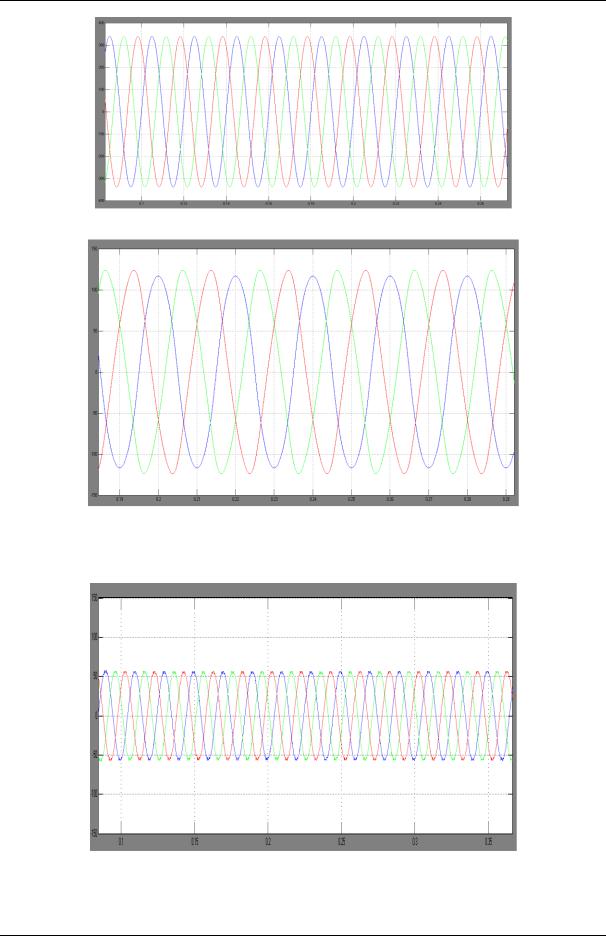
Fig.4 Three Phase source voltages
Fig.5 Three Phase source currents
The effectiveness of the proposed method is demon-strated through simulation result of grid voltage and current shown in Figure 4 &5. This is due to the reference derived from the grid voltage.
Fig.6 Three Phase Load currents
The load current waveform Ia, Ib, Ic are shown in Fig.6 and the inverter output voltage under STATCOM operation with load variation is shown in Figure 7.
www.iosrjen.org |
55 | P a g e |

Power Quality Improvement for Grid Connected Wind Energy System
Fig.7 STATCOM output voltage
Fig.8 Inverter Injected current
Fig.9 Wing Generator current
When STATCOM controller is made ON, without change in any other load condition parameters, it starts to mitigate for reactive demand as well as harmonic current. The dynamic performance is also carried out by step change in a load, when applied at 1.0 s. This additional demand is fulfill by STATCOM compensator. Thus, STATCOM can regulate the available real power from source. While the result of injected current from STATCOM are shown in Fig. 8 and the generated current from wind generator at PCC are depicted in Fig. 9.
Fig.10 DC Link Voltage
www.iosrjen.org |
56 | P a g e |

Power Quality Improvement for Grid Connected Wind Energy System
The DC link voltage regulates the source current in the grid system, so the DC link voltage is maintained constant across the capacitor as shown in Fig. 10.
VI. CONCLUSION
The paper presents the STATCOM-based control scheme for power quality improvement in grid connected wind generating system and with load as DC Motor. The power quality issues and its consequences on the consumer and electric utility are presented. The operation of the control system developed for the STATCOM-BESS in MATLAB/SIMULINK for maintaining the power quality is simulated. It has a capability to cancel out the harmonic parts of the load current. It maintains the source voltage and current in-phase and support the reactive power demand for the wind generator and load at PCC in the grid system, thus it gives an opportunity to enhance the utilization factor of transmission line. The integrated wind generation and STATCOM with BESS have shown the outstanding performance.
REFERENCE
[1].K. S. Hook, Y. Liu, and S. Atcitty, “Mitigation of the wind generation integration related power quality issues by energy storage,” EPQU J., vol. XII, no. 2, 2006.
[2].S.K.Khadem, M. Basu and M.F. Conlon (2010), “Power Quality in Grid connected Renewable Energy Systems: Role of Custom Power Devices” Proceeding of International Conference on Renewable
Energies and Power Quality.
[3].Yuvaraj, Dr.S.N.Deepa (2011), “Improving Grid Power Quality with FACTS Device on Integration of Wind Energy System” Student Pulse Academic Journal Vol. 3 Ref. 4.
[4].F. Zhou, G. Joos, and C. Abhey, “Voltage stability in weak connection wind farm,” in IEEE PES Gen. Meeting, 2005, vol. 2, pp. 1483–1488.
[5].T. Kinjo and T. Senjyu, “Output leveling of renewable energy by electric double layer capacitor applied for energy storage system,” IEEE Trans. Energy Conv., vol. 21, no. 1, Mar. 2006.
[6].R. S. Bhatia, S. P. Jain, D. K. Jain, and B. Singh, “Battery energy storage system for power conditioning of renewable energy sources,” in Proc. Int. Conf. Power Electron Drives System, Jan. 2006, vol. 1, pp. 501–506.
[7].S. W. Mohod and M. V. Aware, “Grid power quality with variable speed wind energy conversion,” in
Proc. IEEE Int. Conf. Power Electronic Drives and Energy System (PEDES), Delhi, Dec. 2006.
[8].Fu. S. Pai and S.-I. Hung, “Design and operation of power converter for microturbine powered distributed generator with capacity expansion capability,” IEEE Trans. Energy Conv., vol. 3, no. 1, pp. 110–116, Mar.2008.
[9].J. A. Barrado, R. Grino, Member IEEE, and H. Valderrama-Blavi, Member IEEE (2010), “PowerQuality Improvement of a Stand-Alone Induction Generator Using a STATCOM With Battery Energy
Storage System” IEEE TRANSACTIONS ON POWER DELIVERY, Vol. 25, No. 4, pp: 342-351.
[10].Kyung Soo KOOK, Yilu LIU, Stan ATCITTY (2006), “Mitigating of the Wind Generation Integration Related Power Quality Issues by Energy Storage” Electrical Power Quality and Utilization, Journal Vol.
12, No. 2, pp: 1097-1109.
[11].M.A. Hannan, A. Mohamed, A. Hussain, Majid AI-Dabbagh (2009), “Power quality analysis of STATCOM using dynamic phasor model-ing” ELSEVIER, Vol.79, pp: 993-999.
[12].Marcelo G.Molina, Pedro E.Mercado, Edson H.Watanabe (2011), “Analysis of integrated STATCOMSMES based on three-phase three-level multi-pulse voltage source inverter for high power utility applications” ELSEVIER, Vol.348, pp: 2350-2377.
www.iosrjen.org |
57 | P a g e |