

1 / zobaa_a_f_cantel_m_m_i_and_bansal_r_ed_power_quality_monitor
.pdfActive Load Balancing in a Three-Phase Network by Reactive Power Compensation |
227 |
depend on the presence or not of neutral conductor and so of the presence or not of zero sequence components of currents. In the following, the two situations are analyzed.
4.1 The generalized Steinmetz circuit for three-phase three-wire networks
A certain three-phase electric load is considered, connected to a three-wire network supplied by a balanced phase to phase voltages set.
In such situations usually can only know the values of the phase currents and phase to phase voltages, network neutral don’t exist or is not accessible.
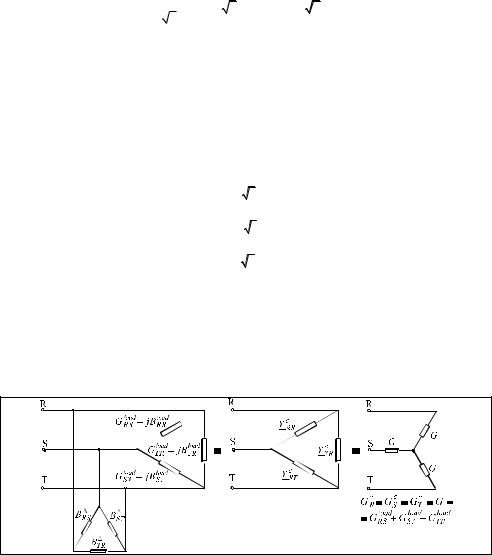
The set of phase to phase voltages is considered symmetrical (Fig. 7b), and the equivalent circuit of the load is taken in connection, whose elements, for practical reasons, are considered like admittances (Fig. 7a).
a) b)
Fig. 7. The equivalent connection with admittances for a certain three-phase load: a) - definition of electrical quantities, b) - phasor diagram of voltages
For the network in figure 7 we therefore have the following sets of equations:
YRS = GRS − j BRS |
YST = GST − j BST |
YTR = GTR − j BTR |
(26) |
|
IRS =URS YRS |
ITR =UTR YTR |
IST =UST YST |
(27) |
|
UR =U |
US = a2 UR = a2 U |
UT = a UR = a U |
(28) |
|
URS =UR −US =U (1− a2 ) |
UST =US −UT =U ( a2 − a ) UTR =UT −UR =U (a − 1) |
(29) |
||
IR = IRS − ITR |
IS = IST − IRS |
IT = ITR − IST |
(30) |
|
Using the equations (26) ÷ (30) it obtains:
|
|
3 |
|
|
|
3 |
|
|
3 |
|
|
|
3 |
|
|
|
|
|
3 |
|
|
|
|
3 |
|
|
|
3 |
|
|
3 |
|
|
|
|||||||||
IR = U |
|
|
|
GRS + |
|
|
|
|
BRS + |
|
|
GTR − |
|
BTR |
+ j |
|
|
|
|
GRS |
− |
|
BRS |
− |
|
|
GTR − |
|
|
|
|
BTR |
|
||||||||||
2 |
2 |
|
2 |
|
2 |
2 |
|
2 |
2 |
|
2 |
|
|||||||||||||||||||||||||||||||
|
|
|
|
|
|
|
|
|
|
|
|
|
|
|
|
|
|
|
|
|
|
|
|
|
|
|
|
|
|||||||||||||||
|
|
|
|
|
|
|
|
|
|
|
|
|
|
|
|
|
|
|
|
|
|
|
|
|
|
|
|
|
|
|
|
|
|
|
|
|
|
|
|
|
|
|
|
|
|
|
|
3 |
|
|
|
|
|
3 |
|
|
|
|
|
|
|
|
|
|
|
|
3 |
|
|
|
|
|
3 |
|
|
|
|
|
|
|
|
|
|
|
|||
IS =U |
|
− |
|
GRS − |
|
|
BRS |
− |
3 BST |
+ j |
− |
|
|
|
|
GRS |
+ |
|
BRS − |
|
3 GST |
|
|
|
(31) |
||||||||||||||||||
2 |
|
2 |
|
|
2 |
2 |
|
|
|||||||||||||||||||||||||||||||||||
|
|
|
|
|
|
|
|
|
|
|
|
|
|
|
|
|
|
|
|
|
|
|
|
|
|
|
|
|
|
|
|
|
|
|
|
|
|||||||
|
|
|
|
|
|
|
|
|
|
|
|
|
|
|
|
|
|
|
|
|
|
|
|
|
|
|
|
|
|
|
|
|
|
|
|
|
|
|
|
|
|
||
|
|
|
|
|
|
|
3 |
|
|
|
|
3 |
|
|
|
|
|
|
|
|
|
|
|
|
3 |
|
|
|
3 |
|
|
|
|
|
|
|
|
|
|
||||
IT =U |
|
|
|
3 BST |
− |
|
|
|
GTR + |
|
|
BTR |
+ j |
|
3 GRS + |
|
|
GTR + |
|
|
BTR |
|
|
|
|
|
|
|
|||||||||||||||
|
|
2 |
|
2 |
|
2 |
|
2 |
|
|
|
|
|
|
|||||||||||||||||||||||||||||
|
|
|
|
|
|
|
|
|
|
|
|
|
|
|
|
|
|
|
|
|
|
|
|
|
|
|
|
|
|
|
|
|
|
|
|
|
|||||||
|
|
|
|
|
|
|
|
|
|
|
|
|
|
|
|
|
|
|
|
|
|
|
|
|
|
|
|
|
|
|
|
|
|
|
|
|
|
|
|
|
|
|
|

228 |
Power Quality – Monitoring, Analysis and Enhancement |
Necessary and sufficient condition for the three phase currents to form a balanced set is the cancellation of the negative sequence current component:
Ii = |
1 |
( IR + a 2 I S + a IT ) = 0 |
(32) |
|
3 |
|
|
Putting the cancellation conditions for the real and imaginary parts of Ii obtained by substituting equations (31) in (32) we obtain the conditions:
|
− GRS + 2 GST − GTR + 3 ( BTR − BRS ) |
= 0 |
|
|
(33) |
||
|
3 (GTR − GRS ) + BRS − 2 BST + BTR = 0 |
|
|
|
|
|
|
|
|
|
|
This system of equations define the relationship that should exist between the six elements of the equivalent connection of a load, so that, from the point of view of the network it appear as a perfectly balanced load (Ii = 0).
These conditions can be obtained by changing (compensating) the equivalent parameters using a parallel compensation circuit, also in connection, so that equations (33) (Gyugyi et al., 1980) to be satisfied for the ensemble load - compensator (Fig. 8).
Fig. 8. The ensemble unbalanced load - shunt compensator
The problem lies in determining the elements of the compensator, so that, knowing the elements of the equivalent circuit of the load, to obtain an ensemble which is perfectly balanced from the point of view of the network, as it means that after the compensation, the currents on the phases satisfy the condition:
IcR = a ISc = a2 ITc |
(34) |
The compensator will not produce changes in the total active power absorbed from the network (which would mean further losses) and hence will contain only reactive elements
( G RS= G ST = G TR= 0 ).
In equations (33) will be replaced so:
Active Load Balancing in a Three-Phase Network by Reactive Power Compensation |
229 |
|||||||
G |
RS |
= Gload |
G |
= Gload ; |
G |
= Gload |
|
|
|
RS |
ST |
ST |
TR |
TR |
(35) |
||
BRS = (BRSload + BRS ) ; |
BST = (BSTload + BST ) ; |
BTR = ( BTRload + BTR ) |
||||||
|
||||||||
From the equations (33) resulting the equation system:
B |
− B |
= A |
|
|
|
RS |
TR |
|
(36) |
|
|
− 2 BST + BTR = B |
||
BRS |
|
|||
|
|
|
|
|
Where:
1 |
|
load |
load |
2 |
|
load |
1 |
load |
load |
|
|
A = − |
|
GRS |
− BRS + |
|
GST − |
|
GTR |
+ BTR |
|
||
3 |
3 |
3 |
(37) |
||||||||
B = 3 GRSload − BRSload + 2 BSTload − |
3 GTRload − BTRload |
|
|||||||||
Unknowns are therefore: B RS |
, BST |
and BTR . |
|
|
|
|
|
||||
With two equations and three unknowns, we are dealing with indeterminacy. A third |
|||||||||||
equation, independent of the first two, which expresses a relationship between the three unknowns, will result by imposing any of the following conditions:
a.full compensation of reactive power demand from network;
b.partial compensation of reactive power demand (up to a required level of power factor);
c.voltage control on the load bus bars trough the control of reactive power demand;
d.install a minimum reactive power for the compensator;
e.minimize active power losses in the supply network of the load.
In this chapter we will consider only the operation of the compensator sized according to the a criterion, other criteria can be treated similarly.
4.1.1 Sizing the compensator elements based on the criterion of total compensation of reactive power demand from the network
According to a criterion, in addition to load balancing, compensation should also lead to cancellation of the reactive power absorbed from the network on the positive sequence ( cosϕ + = 1 ). This is equivalent to the additional condition:
Im(Ic+ ) = 0 |
(38) |
Ic+ is the positive sequence component corresponding to the load current of the ensemble load - compensator. But for this it can write the condition:
|
Ic+ = 1 ( IcR + a ISc + |
a2 ITc ) = IcR , |
(39) |
|
3 |
|
|
because IcR = a ISc |
= a2 ITc , where IcR , ISc and ITc |
are the currents absorbed by the network |
|
after the compensation. As the supplementary condition will be: |
|
||
|
Im(IcR ) = 0 |
(40) |
|
mean: |
G RS − G TR− 3 ( BRS + BTR ) = 0 |
(41) |
|
230 |
Power Quality – Monitoring, Analysis and Enhancement |
Associating now the equations (33) and (41), where the equations (35) are replaced, the system of three equations with three unknowns is obtained:
|
|
|
1 0 |
−1 |
BRS |
A |
|
||||||
|
|
|
1 |
−2 |
1 |
BST |
= B |
(42) |
|||||
|
|
|
1 |
0 |
1 |
|
B |
|
C |
|
|||
|
|
|
|
|
|
|
|
TR |
|
|
|
|
|
where: |
C = |
1 |
( G loadRS − |
3 BloadRS |
− G TRload − |
3 B TRload ) |
(43) |
||||||
3 |
|||||||||||||
|
|
|
|
|
|
|
|
|
|
|
|
||
Solving the system (42) leads to the following solutions:
|
|
BRS = |
1 |
|
|
|
( A + C) |
|
|
|||
|
|
|
|
|
|
|
||||||
|
|
2 |
|
|
|
|
|
|
|
|
||
|
|
|
1 |
|
|
|
|
|
(44) |
|||
|
|
BST = 2 ( B + C) |
|
|||||||||
|
|
|
|
|||||||||
|
|
BTR = |
1 |
|
|
( − A + C ) |
|
|
||||
|
|
|
|
|
|
|||||||
|
|
2 |
|
|
|
|
|
|
|
|
||
|
BRS =− BRSload + |
1 |
( GSTload − GTRload) |
|
||||||||
|
3 |
|
||||||||||
|
|
|
|
|
|
|
|
|
|
) |
|
|
mean: |
B |
= − Bload + |
1 |
|
Gload − Gload |
(45) |
||||||
|
|
|||||||||||
|
ST |
ST |
3 ( TR RS |
|
||||||||
|
BTR =− BTRload + |
|
1 |
(GRSload − GSTload) |
|
|
||||||
|
|
3 |
|
|
||||||||
|
|
|
|
|
|
|
|
|
|
|
|
|
Using now the equations of transformation of a delta connection circuit in a equivalent Y connection circuit, is achieved:
G |
R |
= G = G |
= Gload + Gload + Gload = G |
(46) |
|
S T |
RS ST TR |
||
BR = BS = BT = 0 |
|
|||
These equivalences are illustrated in Figure 9.
Fig. 9. Equivalence of the ensemble load – compensator with a balanced active load

Active Load Balancing in a Three-Phase Network by Reactive Power Compensation |
231 |
4.1.2 The compensation circuit elements expressed by using the sequence components of the load currents
Expressing the compensation circuit elements by using the sequence components of the load currents will allow a full interpretation of the mechanism of compensation.
For this, lets’ consider again the general three-phase unbalanced load, supplied from a balanced three-phase source, without neutral, represented by the equivalent circuit as shown in Fig. 7. The three absorbed load currents will be:
IloadR |
= U YloadRS |
(1 − a2 ) − YTRload (a − 1) |
|
|
|
|
|
|
|
ISload |
= U YSTload |
(a2 − a) − YloadRS |
(1 − a2 ) |
(47) |
|
|
|
|
|
ITload |
= U YTRload |
(a − 1) − YSTload (a2 − a) |
|
|
|
|
|
|
|
We apply the known equations for the sequence components:
Iload+ |
= |
1 |
(IloadR |
+ a ISload + a2 ITload ) |
|
|
|
3 |
|
|
|
Iload− |
= |
1 |
(IloadR |
+ a2 ISload + a ITload ) |
(48) |
|
|
3 |
|
|
|
Iload0 |
= |
1 |
(IloadR |
+ ISload + ITload ) |
|
|
|
3 |
|
|
|
where Iload+ , Iload− and Iload0 are |
the |
positive, negative and |
zero sequence components |
||
(corresponding to the reference phase, R). Replacing the equations (47) in equations (48) the symmetrical components depending on the load admittances are obtained:
Iload+ |
= U (YloadRS + YSTload + YTRload ) |
|
Iload− |
= −U (a2 YloadRS + YSTload + a YTRload ) |
(49) |
Iload0 |
= 0 |
|
Symmetrical components of currents on the compensator phases are obtained by the same way:
I+ = − j (BRS + BST + BTR ) U
I− = j(a2 BRS + BST + a BTR ) U = U 23 (BTR − BRS ) + j U 21 (BRS − 2 BST + BTR ) (50)
I0 = 0
Writing symmetrical components of the phase currents absorbed from the network by the ensemble load - compensator:
Ic+ = Iload+ |
+ I+ |
|
Ic− = Iload− |
+ I− |
(51) |
Ic0 = 0 |
|
|


234 |
|
Power Quality – Monitoring, Analysis and Enhancement |
|||||||||
IRS+ = IST+ = ITR+ = |
|
1 |
|
|
Im( Iload+ ) |
|
|||||
|
3 |
|
|
||||||||
IRS− = − Re( Iload− ) + |
|
|
Im( Iload− |
) |
|||||||
1 |
|
||||||||||
|
|
3 |
|||||||||
|
|
|
|
|
|
|
|
(58) |
|||
|
2 |
Im(Iload− |
) |
|
|||||||
IST− = − |
|
|
|||||||||
3 |
|
|
|||||||||
|
|
|
|
|
|
|
|
|
|
|
|
ITR− = Re( Iload− ) + |
|
1 |
|
Im( Iload− ) |
|
||||||
|
3 |
|
|
||||||||
|
|
|
|
|
|
|
|
|
|
||
With these equations we can determine the currents on the phases of both fictitious compensators, and then the currents flow in symmetrical components, into the ensemble load - compensator.
+ ,− |
|
1 |
|
+ ,− |
+ ,− |
|
|
|
|
3 |
|
+ ,− |
|
3 |
+ ,− |
|
IR |
= |
|
(IRS |
− ITR |
) + j |
− |
|
|
|
IRS |
− |
|
ITR |
|
||
|
|
|
|
|||||||||||||
|
|
2 |
|
|
|
|
|
|
2 |
|
|
|
2 |
|
|
|
|
|
|
|
|
|
|
|
|
|
|
|
|
||||
IS + ,− = − |
1 |
(IRS+ ,− + 2 IST+ ,− ) + j |
|
3 |
IRS+ ,− |
|
|
(59) |
||||||||
2 |
2 |
|
|
|||||||||||||
|
|
|
|
|
|
|
|
|
|
|
|
|
|
|||
IT + ,− = |
1 |
(ITR+ ,− + 2 IST+ ,− ) + j |
|
|
3 |
|
ITR+ ,− |
|
|
|
|
|||||
2 |
|
2 |
|
|
|
|
||||||||||
|
|
|
|
|
|
|
|
|
|
|
|
|
|
|||
+ compensator produces a three-phase set of positive sequence currents, which compensate the reactive component of the positive sequence load current on each phase, and - compensator produces a three-phase set of negative sequence currents, which compensate the negative sequence load current on each phase (both active and reactive component):
|
|
|
|
|
|
|
|
|
|
|
|
|
|
+ |
+ |
+ |
= a |
2 |
|
|
+ |
|
+ |
|
+ |
|
(60) |
IR |
= − j Im(Iload ) IS |
|
|
− j Im(Iload ) |
IT |
= a − j Im(Iload ) |
|||||||
|
IR− = −Iload− |
|
IS − = a (−Iload− |
) IT |
− = a2 (−Iload− ) |
|
|
(61) |
|||||
The currents on the three phases, after compensation, represent a balanced set, positive sequence and contain only the active component (they have zero phase-shift relative to the corresponding phase-to-neutral voltage), equal to the active component of positive sequence load current:
IcR = IloadR |
+ IR+ + IR− = Re( Iload+ ) |
|
|
ISc |
= ISload |
+ IS + + IS − = a2 Re(Iload+ ) |
(62) |
ITc |
= ITload + IT + + IT − = a Re(Iload+ ) |
|
|
Figure 11 shows the compensation mechanism of load currents symmetrical components using phasor diagram.
Starting from the three phasors of unbalanced load currents, considered arbitrary, but check the condition IR + IS + IT = 0 (which means they have a common origin in the center of gravity of the triangle formed by the peaks of the phasors), were determined the reference

Active Load Balancing in a Three-Phase Network by Reactive Power Compensation |
235 |
symmetrical components phasors (corresponding to phase R, Figure 11.a). They will allow
for the determination of the phasors IR+ |
and IR− because: |
|
|
IR |
+ = − Im(Iload+ |
) |
(63) |
IR− = −Iload− |
|
||
|
|
||
a) |
|
|
|
b) |
c) |
|
|
Fig. 11. Phasor diagram illustrating the compensation mechanism of the load current symmetrical components: a) - determination of symmetrical components of reference (phase R), b) - compensation of the negative sequence component, c) - compensation of the imaginary part of the positive sequence component
Currents on the phases of the ensemble load - compensator are then obtained, first by compensating the negative sequence (Figure 11.b) and then by compensating the positive sequence (Figure 11.c) realized on the basis of equations:
