- •GENERAL INFORMATION
- •SERVICE ADJUSTMENTS
- •MASTER CYLINDER FLUID LEVEL
- •ABS BRAKES
- •ADJUSTING REAR SERVICE BRAKES
- •TESTING APPLICATION ADJUSTER OPERATION
- •BLEEDING BRAKE SYSTEM
- •PRESSURE BLEEDING
- •BLEEDING WITHOUT A PRESSURE BLEEDER
- •TEST FOR FLUID CONTAMINATION
- •WHEEL STUD NUT TIGHTENING
- •BRAKE HOSE AND TUBING
- •INSPECTION OF BRAKE HOSE AND TUBING
- •FIG. 10 BRAKE LINE ROUTING NON ABS BRAKES
- •INSTALLATION OF BRAKE HOSE
- •TYPES OF TUBING FLARES
- •TO REPAIR OR FLARE TUBING
- •ISO TUBING FLARES
- •BASIC DIAGNOSIS GUIDE
- •BRAKE SYSTEM DIAGNOSTICS
- •BRAKE SYSTEM DIAGNOSTICS
- •BRAKE SYSTEM DIAGNOSTICS
- •BRAKE SYSTEM DIAGNOSTICS
- •REAR WHEEL DRUM BRAKES
- •DESCRIPTION
- •SERVICE PROCEDURES
- •REAR BRAKE DRUM REMOVAL
- •BRAKE DRUM INSTALLATION
- •BRAKE SHOE ASSEMBLIES
- •REMOVAL
- •CLEANING AND INSPECTION
- •BRAKE SHOE INSTALLATION
- •KELSEY HAYES REASSEMBLE
- •VARGA REASSEMBLE
- •BRAKE DRUM REFACING
- •WHEEL CYLINDERS
- •GENERAL INFORMATION
- •SERVICE PROCEDURES
- •REMOVING WHEEL CYLINDERS FROM BRAKE SUPPORT PLATES
- •DISASSEMBLING WHEEL CYLINDERS
- •ASSEMBLING WHEEL CYLINDERS
- •INSTALLING WHEEL CYLINDERS
- •BRAKE SUPPORT ASSEMBLY
- •REMOVAL
- •INSTALLATION
- •HYDRAULIC SYSTEM CONTROL VALVES
- •GENERAL INFORMATION
- •PRESSURE DIFFERENTIAL WARNING LIGHT SWITCH
- •ABS BRAKE PROPORTIONING VALVE OPERATION
- •HYDRAULIC SYSTEM SERVICE PROCEDURES
- •BRAKE WARNING SYSTEM
- •PROPORTIONING VALVES
- •PROPORTIONING VALVE APPLICATIONS
- •TESTING ABS PROPORTIONING VALVES
- •FRONT DISC BRAKES
- •GENERAL INFORMATION
- •SHOE AND LINING WEAR
- •SERVICE PRECAUTIONS
- •KELSEY HAYES DOUBLE PIN FAMILY CALIPER
- •BRAKE SHOE SERVICE PROCEDURES
- •REMOVAL
- •INSTALLATION
- •SERVICE PROCEDURES
- •BRAKE SHOES REMOVE
- •CLEANING AND INSPECTION
- •BRAKE SHOES INSTALL
- •DISC BRAKE CALIPER DISASSEMBLY
- •CLEANING AND INSPECTION
- •CLEANING AND INSPECTION OF BRAKE CALIPER
- •ASSEMBLING DISC BRAKE CALIPER
- •REAR DISC BRAKES
- •GENERAL INFORMATION
- •LINING WEAR
- •SERVICE PRECAUTIONS
- •BRAKE SHOE REMOVAL
- •CLEANING AND INSPECTION
- •BRAKE SHOE INSTALLATION
- •DISASSEMBLING REAR CALIPER ASSEMBLY
- •CLEANING AND INSPECTION
- •CLEANING AND INSPECTION
- •ASSEMBLING REAR DISC BRAKE CALIPER
- •BRAKE DISC (ROTOR)
- •GENERAL INFORMATION
- •INSPECTION DIAGNOSIS
- •SERVICE PROCEDURES
- •CHECKING BRAKING DISC FOR RUNOUT AND THICKNESS
- •BRAKING DISC REMOVAL
- •INSTALLING BRAKING DISC
- •REFINISHING BRAKING DISC
- •REFACING BRAKING DISC
- •RESURFACING BRAKING DISC
- •BRAKING DISC (ROTOR) REFINISHING LIMITS
- •PARKING BRAKES
- •GENERAL INFORMATION
- •SERVICE PROCEDURES
- •ADJUSTING PARKING BRAKE
- •FIG. 2 PARKING BRAKE CABLE ROUTING AA AND AP BODY
- •FIG. 4 PARKING BRAKE CABLE ROUTING AG AND AJ BODY
- •SELF ADJUSTING PROCEDURES
- •TO RELOAD SELF ADJUSTER
- •ADJUST PARKING BRAKE
- •REAR PARKING BRAKE CABLE REMOVAL
- •DRUM BRAKES
- •DISC BRAKES
- •INSTALLING PARKING BRAKE REAR CABLE
- •DRUM BRAKES
- •DISC BRAKES ALL
- •REMOVING PARKING BRAKE FRONT CABLE
- •INSTALLING PARKING BRAKE FRONT CABLE
- •REMOVAL AG AND AJ BODY
- •INSTALLATION AG AND AJ BODY
- •REMOVAL AND INSTALLATION PARKING BRAKE SHOES
- •ALL WITH REAR DISC BRAKES
- •INSTALLING PARKING BRAKE SHOES
- •MASTER CYLINDER
- •GENERAL INFORMATION
- •BRAKE FLUID LEVEL SENSOR
- •TESTING THE MASTER CYLINDER
- •MASTER CYLINDER SERVICE PROCEDURES
- •MASTER CYLINDER REMOVAL
- •BRAKE FLUID RESERVOIR REPLACEMENT
- •BLEEDING MASTER CYLINDER
- •INSTALLING MASTER CYLINDER
- •POWER BRAKES
- •GENERAL INFORMATION
- •SERVICE PROCEDURES
- •POWER BRAKE BOOSTER ASSEMBLY
- •WHEEL BEARINGS
- •FRONT WHEEL BEARINGS
- •REAR WHEEL BEARINGS
- •NORMAL SERVICE
- •INSPECTION
- •REMOVAL AND INSTALLATION
- •GENERAL INFORMATION
- •NORMAL BRAKING SYSTEM FUNCTION
- •MAJOR ABS COMPONENTS
- •HYDRAULIC ASSEMBLY
- •WHEEL SPEED SENSORS
- •NORMAL BRAKING SYSTEM FUNCTION
- •PEDAL FEEL
- •TIRE NOISE & MARKS
- •ABS EQUIPPED VEHICLE PERFORMANCE
- •ABS WARNING SYSTEMS OPERATION
- •RED BRAKE WARNING LAMP
- •NORMAL OPERATION OF WARNING LAMPS
- •HYDRAULIC ASSEMBLY
- •HYDRAULIC BLADDER ACCUMULATOR
- •DUAL FUNCTION PRESSURE SWITCH
- •PRESSURE TRANSDUCERS
- •DIFFERENTIAL PRESSURE SWITCH
- •PROPORTIONING VALVES
- •FLUID LEVEL SWITCH
- •DUAL FUNCTION PRESSURE SWITCH WIRING DIAGRAM
- •WHEEL SPEED SENSORS
- •PRESSURE SWITCH AND PRESSURE TRANSDUCER WIRING
- •ABS SYSTEM WIRING SCHEMATIC
- •ABS SYSTEM DIAGNOSTIC CONNECTOR
- •SYSTEM RELAY
- •ABS HYDRAULIC CIRCUITS AND VALVE OPERATION
- •NORMAL BRAKING
- •ABS BRAKING SYSTEM DIAGNOSIS
- •GENERAL INFORMATION
- •DEFINITIONS
- •ABS SYSTEM GENERAL SERVICE PRECAUTIONS
- •TEST DRIVING ABS COMPLAINT VEHICLES
- •WHEEL SPEED SENSOR CABLES
- •SPECIAL SERVICE TOOLS
- •INTERMITTENT FAULTS
- •ABS BRAKE SYSTEM DIAGNOSTIC FEATURES
- •SYSTEM SELF DIAGNOSIS
- •BENDIX ABS SYSTEMS DIAGNOSTICS
- •ON CAR HYDRAULIC ABS COMPONENT SERVICE
- •GENERAL SERVICE PRECAUTIONS
- •CHECKING BRAKE FLUID LEVEL
- •BLEEDING ABS BRAKE SYSTEM
- •BRAKE FLUID PRESSURE AND RETURN HOSES (FIG. 6)
- •INSTALL
- •HYDRAULIC ASSEMBLY
- •BRAKE FLUID RESERVOIR
- •HYDRAULIC BLADDER ACCUMULATOR
- •PROPORTIONING VALVES (FIG. 17)
- •ELECTRONIC COMPONENTS
- •WHEEL SPEED SENSORS
- •FRONT WHEEL SPEED SENSOR
- •REAR WHEEL SPEED SENSOR (FIGS. 13 AND 15)
- •GENERAL INFORMATION
- •NORMAL BRAKING SYSTEM FUNCTION
- •MAJOR COMPONENTS
- •MASTER CYLINDER AND VACUUM BOOSTER
- •WHEEL SPEED SENSORS
- •PEDAL FEEL
- •TIRE NOISE & MARKS
- •VEHICLE PERFORMANCE
- •WARNING SYSTEMS OPERATION
- •NORMAL OPERATION OF WARNING LAMP
- •MODULATOR ASSEMBLY
- •ISOLATION VALVES
- •SHUTTLE ORIFICE
- •FLUID SUMPS
- •HYDRAULIC SPRING ACCUMULATOR
- •PROPORTIONING VALVES
- •WHEEL SPEED SENSORS
- •DIAGNOSTIC CONNECTOR
- •SYSTEM RELAY
- •HYDRAULIC CIRCUITS AND VALVE OPERATION
- •NORMAL BRAKING
- •ABS BRAKE SYSTEM DIAGNOSIS
- •GENERAL INFORMATION
- •DEFINITIONS
- •ABS COMPUTER SYSTEM SERVICE PRECAUTIONS
- •ABS GENERAL SERVICE PRECAUTIONS
- •TEST DRIVING ABS COMPLAINT VEHICLES
- •ABS BRAKE SYSTEM ON VEHICLE SERVICE
- •WHEEL SPEED SENSOR CABLES
- •SPECIAL SERVICE TOOL
- •INTERMITTENT FAULTS
- •ABS BRAKE SYSTEM DIAGNOSTIC FEATURES
- •ABS SYSTEM SELF DIAGNOSIS
- •BENDIX ABS SYSTEMS DIAGNOSTICS
- •GENERAL SERVICE PRECAUTIONS
- •CHECKING BRAKE FLUID LEVEL
- •MODULATOR ASSEMBLY (FIG. 2)
- •MASTER CYLINDER AND POWER BOOSTER
- •PROPORTIONING VALVES (FIG. 5)
- •ELECTRONIC COMPONENTS
- •WHEEL SPEED SENSORS
- •FRONT WHEEL SPEED SENSOR (FIG. 12)
- •REAR WHEEL SPEED SENSOR (FIGS. 13 AND 14)
- •SPECIFICATIONS
- •SPECIFICATIONS METRIC
- •BRAKE ACTUATION SYSTEM
- •TIGHTENING REFERENCE

Ä |
|
BRAKES 5 - 21 |
|
Fig. 10 Adjuster Screw and Lever (Typical)
If old springs have overheated or are damaged, replace. Overheating indications are paint discoloration or distorted end coils.
BRAKE SHOE INSTALLATION
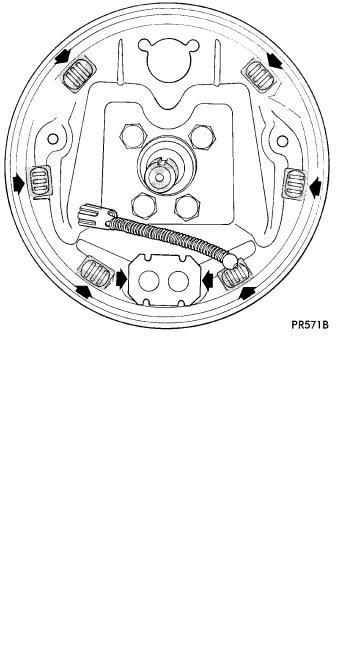
Lubricate the eight shoe contact areas on the support plate and anchor using Mopar Multi-Purpose Lubricant or equivalent (Fig. 11).
Fig. 11 Shoe Contact Areas on Support Plate
KELSEY HAYES REASSEMBLE
Assemble the park brake lever and wave washer to the new replacement shoe (Fig. 9).
Attach upper return spring between the two new shoe assemblies.
Apply a small amount of Mopar Multi-Purpose Lubricant or equivalent to the automatic adjuster screw assembly. Install adjuster with the two stepped forks facing toward the outboard side of the shoes (Fig. 10). The longer fork will be pointing to the rear.
Connect the lower shoe to shoe spring.
Expand the automatic adjuster so that the end of the shoes will clear the wheel cylinder boots. Position
the brake shoe assemblies on support plate and install holddown springs (Fig. 7).
Install self adjuster lever and spring. Connect park brake cable.
Adjust brake shoes so that they will not interfere with the drum installation.
CAUTION: Make sure the adjuster screw nut contacts the adjuster tubular strut.
Install the drums and pump the brake pedal several times to partially complete the shoe adjustment.
After adjusting the Parking brake cable (see Adjusting Parking Brake), road test vehicle. The automatic adjuster will continue the brake adjustment during the test.
VARGA REASSEMBLE
Assemble the park brake lever and wave washer to the new trailing shoe. Install retainer and close retainer ends (Fig. 9).
Install park brake cable in park brake lever of trailing shoe.
Attach trailing shoe, then leading shoe lower springs to shoes and anchor plate.
Position shoes on support plate and install holddown springs.
Install automatic adjusters. Left side adjuster has left hand threads and right side adjuster has right-hand threads. Do not interchange sides. Make sure adjuster is installed correctly. (Adjuster ends must be above extruded pins in web of shoe as shown in Fig. 3).
Install upper shoe to shoe spring. Ensure that the spring terminal ends are fully engaged in the shoe webs.
Rotate serrated adjuster nut to remove free play from the adjuster assembly.
Install the adjuster lever on the leading shoe pivot pin. Then attach the short end of the adjuster spring into the hole on the lever. Then install the long end of the spring in the leading shoe hole.
Connect park brake cable and adjust brake shoes so as not to interfere with drum installation.
BRAKE DRUM REFACING
Measure drum runout and diameter. If not to specification, reface drum. (Runout should not exceed 0.1524 mm or 0.006 inch). The diameter variation (oval shape) of the drum braking surface must not exceed either 0.0635 mm (0.0025 inch) in 30° or 0.0889 mm (0.0035 inch) in 360°.
All drums will show markings of maximum allowable diameter (Fig. 12).
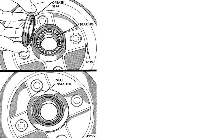
Using suitable tool, remove grease seal from drum hub. Clean, inspect and pack wheel bearings. Install new seal (Fig. 13). See Wheel Bearings section in

5 - 22 BRAKES |
|
Ä |
|
this group of the service manual for detailed information on the wheel bearings, and service procedures.
Fig. 12 Maximum Drum Diameter Identification
Fig. 13 Installing Grease Seal
