


Ä |
|
ANTI-LOCK 10 BRAKE SYSTEM 5 - 79 |
|
PRESSURE SWITCH AND PRESSURE TRANSDUCER WIRING
fluid condition exists the switch will close, grounding the low fluid circuit and illuminating the Red Brake Warning Lamp. The (CAB) will disable the Anti-Lock Function and light the Amber Anti-Lock Warning Lamp if the vehicle is in motion above 3 mph. If the vehicle is not in motion, the Amber Anti-Lock Warning Lamp will NOT be lit.
PUMP/MOTOR ASSEMBLY
NOTE: The (CAB) does not control the operation of the pump/motor assembly.
The Pump/Motor Assembly is mounted to the transaxle below the hydraulic assembly,(Fig. 3). Integral to the Pump/Motor Assembly is an accumulator using a sliding piston configuration with a nitrogen precharge of 3,172 kPa (460 psi.) The Pump/Motor is an electrically driven pump that takes low pressure brake fluid from the hydraulic assembly fluid reservoir and pressurizes it. The pressurized fluid is then stored in the piston accumulator and hydraulic bladder accumulator for power assist and Anti-Lock Braking. Operation of the Pump/Motor is controlled by the Dual Function Pressure Switch through the Pump/Motor Relay. The (CAB) does NOT control the Pump/Motor activation. Rubber isolators are used to mount the pump to its bracket for noise isolation. The Pump/Motor Assembly is connected to the Hydraulic Assembly with a low pressure return hose and a high pressure hose. A filter is located in the low pressure return line.
WHEEL SPEED SENSORS
One Wheel Speed Sensor (WSS), is located at each wheel (Figs. 4, 5 and 6) and sends a small (AC) electrical signal to the control module (CAB). This signal is generated by magnetic induction. The mag-
Fig. 3 Pump/Motor Assembly And Heat Shield
netic induction is created when a toothed sensor ring (Tone Wheel) passes by the stationary magnetic (Wheel Speed Sensor). The (CAB) converts the (AC) electrical signal generated at each wheel into a digital signal. If a wheel locking tendency is detected, the (CAB) will then modulate hydraulic pressure to prevent the wheel(s) from locking.
The front Wheel Speed Sensor (Fig. 4) is mounted to a boss on the steering knuckle, for both the Front Wheel Drive and All Wheel Drive applications. The Tone Wheel is part of the outboard constant velocity joint housing.
The Rear Wheel Speed Sensor, is mounted to the caliper mounting adapter (Fig. 5). The rear Tone
5 - 80 ANTI-LOCK 10 BRAKE SYSTEM |
|
Ä |
|
Fig. 4 Front Wheel Speed Sensor
Wheel is an integral part of the rear disc brake rotor hub (Fig. 6).
Fig. 5 Rear Wheel Speed Sensor
The speed sensor, to tone wheel air gap on all applications is NOT adjustable.
All 4 of the vehicles, Wheel Speed Sensors are serviced individually as replaceable components.
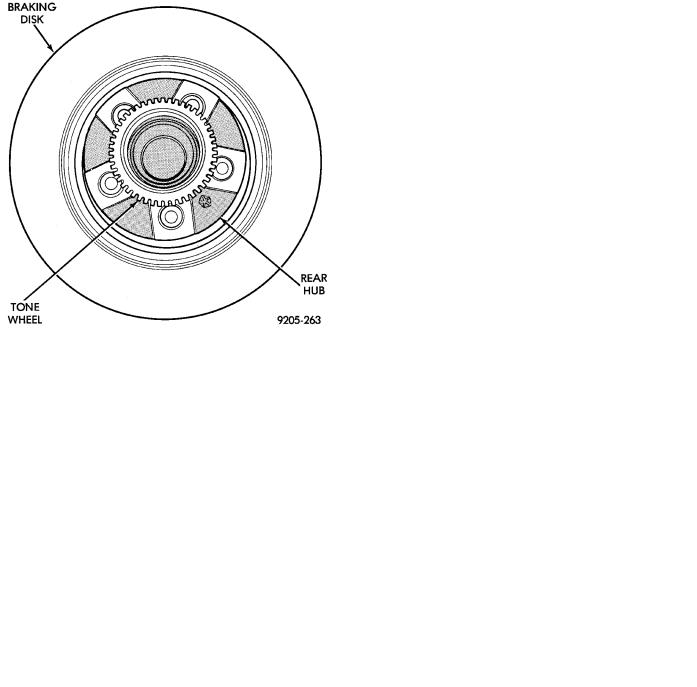
Fig. 6 Rear Tone Wheel
The Front Wheel Drive front Tone Wheels are serviced as an assembly with the front outboard constant velocity joint housings. The rear Tone Wheels are serviced as an assembly with the rear disc brake rotor hub.
Correct Anti-Lock System operation is dependent on wheel speed signals from the wheel speed sensors. The vehicles' wheels and tires must all be the same size and type to generate accurate signals. In addition, the tires must be inflated to the recommended pressures for optimum system operation. Variations in wheel and tire size or significant variations in inflation pressure can produce inaccurate wheel speed signals.
CONTROLLER ANTI-LOCK BRAKE (CAB)
The Anti-Lock Brake Controller is a small microprocessor based device that monitors the brake system and controls the system while it functions in AntiLock Mode. The CAB is located under the battery tray and is mounted to the left frame rail (Fig. 7) and uses a 60-way system connector. The power source for the CAB is through the ignition switch to pin 60 of the controller. With the ignition in the RUN or ON position. IF THE (ABS) CONTROLLER NEEDS
TO BE REPLACED BE SURE THE CORRECT CONTROLLER IS USED. THE CONTROLLER ANTI-LOCK BRAKE (CAB) IS NOT ON THE CCD BUS.
Ä |
|
ANTI-LOCK 10 BRAKE SYSTEM 5 - 81 |
|