- •GENERAL INFORMATION
- •SERVICE ADJUSTMENTS
- •MASTER CYLINDER FLUID LEVEL
- •ABS BRAKES
- •ADJUSTING REAR SERVICE BRAKES
- •TESTING APPLICATION ADJUSTER OPERATION
- •BLEEDING BRAKE SYSTEM
- •PRESSURE BLEEDING
- •BLEEDING WITHOUT A PRESSURE BLEEDER
- •TEST FOR FLUID CONTAMINATION
- •WHEEL STUD NUT TIGHTENING
- •BRAKE HOSE AND TUBING
- •INSPECTION OF BRAKE HOSE AND TUBING
- •FIG. 10 BRAKE LINE ROUTING NON ABS BRAKES
- •INSTALLATION OF BRAKE HOSE
- •TYPES OF TUBING FLARES
- •TO REPAIR OR FLARE TUBING
- •ISO TUBING FLARES
- •BASIC DIAGNOSIS GUIDE
- •BRAKE SYSTEM DIAGNOSTICS
- •BRAKE SYSTEM DIAGNOSTICS
- •BRAKE SYSTEM DIAGNOSTICS
- •BRAKE SYSTEM DIAGNOSTICS
- •REAR WHEEL DRUM BRAKES
- •DESCRIPTION
- •SERVICE PROCEDURES
- •REAR BRAKE DRUM REMOVAL
- •BRAKE DRUM INSTALLATION
- •BRAKE SHOE ASSEMBLIES
- •REMOVAL
- •CLEANING AND INSPECTION
- •BRAKE SHOE INSTALLATION
- •KELSEY HAYES REASSEMBLE
- •VARGA REASSEMBLE
- •BRAKE DRUM REFACING
- •WHEEL CYLINDERS
- •GENERAL INFORMATION
- •SERVICE PROCEDURES
- •REMOVING WHEEL CYLINDERS FROM BRAKE SUPPORT PLATES
- •DISASSEMBLING WHEEL CYLINDERS
- •ASSEMBLING WHEEL CYLINDERS
- •INSTALLING WHEEL CYLINDERS
- •BRAKE SUPPORT ASSEMBLY
- •REMOVAL
- •INSTALLATION
- •HYDRAULIC SYSTEM CONTROL VALVES
- •GENERAL INFORMATION
- •PRESSURE DIFFERENTIAL WARNING LIGHT SWITCH
- •ABS BRAKE PROPORTIONING VALVE OPERATION
- •HYDRAULIC SYSTEM SERVICE PROCEDURES
- •BRAKE WARNING SYSTEM
- •PROPORTIONING VALVES
- •PROPORTIONING VALVE APPLICATIONS
- •TESTING ABS PROPORTIONING VALVES
- •FRONT DISC BRAKES
- •GENERAL INFORMATION
- •SHOE AND LINING WEAR
- •SERVICE PRECAUTIONS
- •KELSEY HAYES DOUBLE PIN FAMILY CALIPER
- •BRAKE SHOE SERVICE PROCEDURES
- •REMOVAL
- •INSTALLATION
- •SERVICE PROCEDURES
- •BRAKE SHOES REMOVE
- •CLEANING AND INSPECTION
- •BRAKE SHOES INSTALL
- •DISC BRAKE CALIPER DISASSEMBLY
- •CLEANING AND INSPECTION
- •CLEANING AND INSPECTION OF BRAKE CALIPER
- •ASSEMBLING DISC BRAKE CALIPER
- •REAR DISC BRAKES
- •GENERAL INFORMATION
- •LINING WEAR
- •SERVICE PRECAUTIONS
- •BRAKE SHOE REMOVAL
- •CLEANING AND INSPECTION
- •BRAKE SHOE INSTALLATION
- •DISASSEMBLING REAR CALIPER ASSEMBLY
- •CLEANING AND INSPECTION
- •CLEANING AND INSPECTION
- •ASSEMBLING REAR DISC BRAKE CALIPER
- •BRAKE DISC (ROTOR)
- •GENERAL INFORMATION
- •INSPECTION DIAGNOSIS
- •SERVICE PROCEDURES
- •CHECKING BRAKING DISC FOR RUNOUT AND THICKNESS
- •BRAKING DISC REMOVAL
- •INSTALLING BRAKING DISC
- •REFINISHING BRAKING DISC
- •REFACING BRAKING DISC
- •RESURFACING BRAKING DISC
- •BRAKING DISC (ROTOR) REFINISHING LIMITS
- •PARKING BRAKES
- •GENERAL INFORMATION
- •SERVICE PROCEDURES
- •ADJUSTING PARKING BRAKE
- •FIG. 2 PARKING BRAKE CABLE ROUTING AA AND AP BODY
- •FIG. 4 PARKING BRAKE CABLE ROUTING AG AND AJ BODY
- •SELF ADJUSTING PROCEDURES
- •TO RELOAD SELF ADJUSTER
- •ADJUST PARKING BRAKE
- •REAR PARKING BRAKE CABLE REMOVAL
- •DRUM BRAKES
- •DISC BRAKES
- •INSTALLING PARKING BRAKE REAR CABLE
- •DRUM BRAKES
- •DISC BRAKES ALL
- •REMOVING PARKING BRAKE FRONT CABLE
- •INSTALLING PARKING BRAKE FRONT CABLE
- •REMOVAL AG AND AJ BODY
- •INSTALLATION AG AND AJ BODY
- •REMOVAL AND INSTALLATION PARKING BRAKE SHOES
- •ALL WITH REAR DISC BRAKES
- •INSTALLING PARKING BRAKE SHOES
- •MASTER CYLINDER
- •GENERAL INFORMATION
- •BRAKE FLUID LEVEL SENSOR
- •TESTING THE MASTER CYLINDER
- •MASTER CYLINDER SERVICE PROCEDURES
- •MASTER CYLINDER REMOVAL
- •BRAKE FLUID RESERVOIR REPLACEMENT
- •BLEEDING MASTER CYLINDER
- •INSTALLING MASTER CYLINDER
- •POWER BRAKES
- •GENERAL INFORMATION
- •SERVICE PROCEDURES
- •POWER BRAKE BOOSTER ASSEMBLY
- •WHEEL BEARINGS
- •FRONT WHEEL BEARINGS
- •REAR WHEEL BEARINGS
- •NORMAL SERVICE
- •INSPECTION
- •REMOVAL AND INSTALLATION
- •GENERAL INFORMATION
- •NORMAL BRAKING SYSTEM FUNCTION
- •MAJOR ABS COMPONENTS
- •HYDRAULIC ASSEMBLY
- •WHEEL SPEED SENSORS
- •NORMAL BRAKING SYSTEM FUNCTION
- •PEDAL FEEL
- •TIRE NOISE & MARKS
- •ABS EQUIPPED VEHICLE PERFORMANCE
- •ABS WARNING SYSTEMS OPERATION
- •RED BRAKE WARNING LAMP
- •NORMAL OPERATION OF WARNING LAMPS
- •HYDRAULIC ASSEMBLY
- •HYDRAULIC BLADDER ACCUMULATOR
- •DUAL FUNCTION PRESSURE SWITCH
- •PRESSURE TRANSDUCERS
- •DIFFERENTIAL PRESSURE SWITCH
- •PROPORTIONING VALVES
- •FLUID LEVEL SWITCH
- •DUAL FUNCTION PRESSURE SWITCH WIRING DIAGRAM
- •WHEEL SPEED SENSORS
- •PRESSURE SWITCH AND PRESSURE TRANSDUCER WIRING
- •ABS SYSTEM WIRING SCHEMATIC
- •ABS SYSTEM DIAGNOSTIC CONNECTOR
- •SYSTEM RELAY
- •ABS HYDRAULIC CIRCUITS AND VALVE OPERATION
- •NORMAL BRAKING
- •ABS BRAKING SYSTEM DIAGNOSIS
- •GENERAL INFORMATION
- •DEFINITIONS
- •ABS SYSTEM GENERAL SERVICE PRECAUTIONS
- •TEST DRIVING ABS COMPLAINT VEHICLES
- •WHEEL SPEED SENSOR CABLES
- •SPECIAL SERVICE TOOLS
- •INTERMITTENT FAULTS
- •ABS BRAKE SYSTEM DIAGNOSTIC FEATURES
- •SYSTEM SELF DIAGNOSIS
- •BENDIX ABS SYSTEMS DIAGNOSTICS
- •ON CAR HYDRAULIC ABS COMPONENT SERVICE
- •GENERAL SERVICE PRECAUTIONS
- •CHECKING BRAKE FLUID LEVEL
- •BLEEDING ABS BRAKE SYSTEM
- •BRAKE FLUID PRESSURE AND RETURN HOSES (FIG. 6)
- •INSTALL
- •HYDRAULIC ASSEMBLY
- •BRAKE FLUID RESERVOIR
- •HYDRAULIC BLADDER ACCUMULATOR
- •PROPORTIONING VALVES (FIG. 17)
- •ELECTRONIC COMPONENTS
- •WHEEL SPEED SENSORS
- •FRONT WHEEL SPEED SENSOR
- •REAR WHEEL SPEED SENSOR (FIGS. 13 AND 15)
- •GENERAL INFORMATION
- •NORMAL BRAKING SYSTEM FUNCTION
- •MAJOR COMPONENTS
- •MASTER CYLINDER AND VACUUM BOOSTER
- •WHEEL SPEED SENSORS
- •PEDAL FEEL
- •TIRE NOISE & MARKS
- •VEHICLE PERFORMANCE
- •WARNING SYSTEMS OPERATION
- •NORMAL OPERATION OF WARNING LAMP
- •MODULATOR ASSEMBLY
- •ISOLATION VALVES
- •SHUTTLE ORIFICE
- •FLUID SUMPS
- •HYDRAULIC SPRING ACCUMULATOR
- •PROPORTIONING VALVES
- •WHEEL SPEED SENSORS
- •DIAGNOSTIC CONNECTOR
- •SYSTEM RELAY
- •HYDRAULIC CIRCUITS AND VALVE OPERATION
- •NORMAL BRAKING
- •ABS BRAKE SYSTEM DIAGNOSIS
- •GENERAL INFORMATION
- •DEFINITIONS
- •ABS COMPUTER SYSTEM SERVICE PRECAUTIONS
- •ABS GENERAL SERVICE PRECAUTIONS
- •TEST DRIVING ABS COMPLAINT VEHICLES
- •ABS BRAKE SYSTEM ON VEHICLE SERVICE
- •WHEEL SPEED SENSOR CABLES
- •SPECIAL SERVICE TOOL
- •INTERMITTENT FAULTS
- •ABS BRAKE SYSTEM DIAGNOSTIC FEATURES
- •ABS SYSTEM SELF DIAGNOSIS
- •BENDIX ABS SYSTEMS DIAGNOSTICS
- •GENERAL SERVICE PRECAUTIONS
- •CHECKING BRAKE FLUID LEVEL
- •MODULATOR ASSEMBLY (FIG. 2)
- •MASTER CYLINDER AND POWER BOOSTER
- •PROPORTIONING VALVES (FIG. 5)
- •ELECTRONIC COMPONENTS
- •WHEEL SPEED SENSORS
- •FRONT WHEEL SPEED SENSOR (FIG. 12)
- •REAR WHEEL SPEED SENSOR (FIGS. 13 AND 14)
- •SPECIFICATIONS
- •SPECIFICATIONS METRIC
- •BRAKE ACTUATION SYSTEM
- •TIGHTENING REFERENCE
Ä |
|
BRAKES 5 - 1 |
|
BRAKES
CONTENTS
|
page |
ANTI-LOCK BRAKE SYSTEMÐBENDIX |
|
ANTI-LOCK 10 AC/Y BODY . . . . . . . . . . |
. . . . 72 |
ANTI-LOCK BRAKE SYSTEMÐBENDIX |
|
ANTI-LOCK 6 AA,AG,AJ BODY . . . . . . . . |
. . 105 |
BRAKE DISC (ROTOR) . . . . . . . . . . . . . . . . |
. . 53 |
BRAKE SUPPORT ASSEMBLY . . . . . . . . . . |
. . 25 |
FRONT DISC BRAKES . . . . . . . . . . . . . . . . . |
. . 31 |
GENERAL INFORMATION . . . . . . . . . . . . . . |
. . 1 |
HYDRAULIC SYSTEM CONTROL VALVES |
. . . 26 |
KELSEY HAYES DOUBLE PIN FAMILY |
|
CALIPER . . . . . . . . . . . . . . . . . . . . . . . . . . |
. . 35 |
|
page |
KELSEY HAYES DOUBLE PIN NON-FAMILY |
|
CALIPER . . . . . . . . . . . . . . . . . . . . . . . . . . . . |
. 38 |
MASTER CYLINDER . . . . . . . . . . . . . . . . . . . . |
. 66 |
PARKING BRAKES . . . . . . . . . . . . . . . . . . . . . |
. 57 |
POWER BRAKES . . . . . . . . . . . . . . . . . . . . . . . |
. 68 |
REAR DISC BRAKES . . . . . . . . . . . . . . . . . . . . |
. 45 |
REAR WHEEL DRUM BRAKES . . . . . . . . . . . . |
. 18 |
SERVICE ADJUSTMENTS . . . . . . . . . . . . . . . . |
. 4 |
WHEEL BEARINGS . . . . . . . . . . . . . . . . . . . . . |
. 70 |
WHEEL CYLINDERS . . . . . . . . . . . . . . . . . . . . |
. 23 |
GENERAL INFORMATION
Throughout this group, references may be made to a particular vehicle by letter or number designation. A chart showing the break down of these designations is included in the Introduction Section at the front of this service manual.
Standard brake equipment consists of:
²Double pin floating caliper disc front brakes.
²Rear automatic adjusting drum brakes.
²Differential valve with a brake warning switch.
²Master cylinder.
²Vacuum power booster.
²Double pin floating caliper rear disc brakes are available on some models.
The Anti-Lock braking system. Uses the standard power brake system caliper assemblies, braking discs, pedal assembly, brake lines and hoses. The unique parts of the Anti-Lock braking system consists of the following components. Unique proportioning valves, wheel speed sensors, tone wheels, electronic control units, modulator assembly and hydraulic assembly which replaces the conventional master cylinder and power booster. These components will be described in detail in the Anti-Lock brake section in this group of the service manual.
The front disc brake shoes have semi-metallic linings.
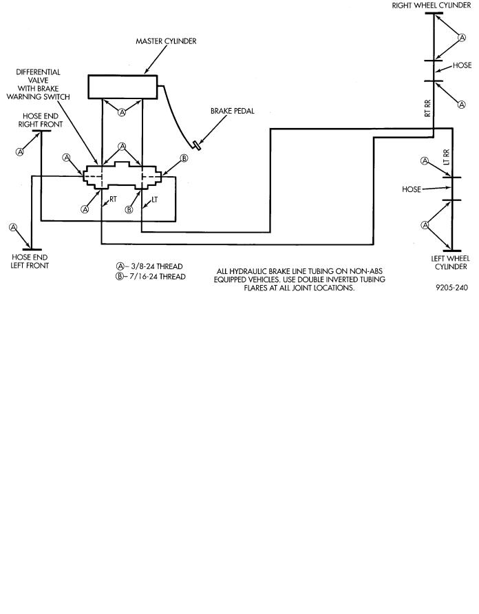
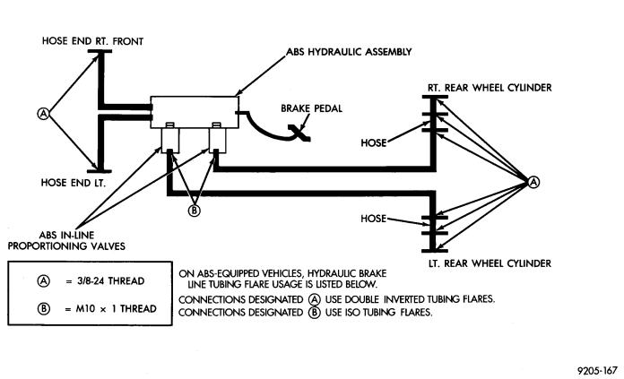
The hydraulic brake system (Figs. 1, 2 and 3) is diagonally split on both the Non-ABS and ABS braking system. With the left front and right rear brakes on one hydraulic system and the right front and left rear on the other.
The Non-ABS and ABS brake system uses different types of brake line fittings and tubing flares. The Non-ABS brake system uses double wall tubing flares and fittings at all tubing joint locations. The ABS brake system uses both ISO style tubing flares and double wall tubing flares and corresponding fittings at different joint locations. See (Figs. 2 and 3) for specific joint locations and type of tubing flare.
The front disc brakes consist of two different types of caliper assemblies. The double pin Kelsey-Hayes caliper (family caliper) with a bolt-on adapter attached to the steering knuckle, or a double pin Kelsey-Hayes caliper which mounts directly to rails on the steering knuckle. The non-family caliper.
CAUTION: Caliper pistons, boots and seals for the different caliper assemblies used on the front and rear disc brake assemblies are not interchangeable. Misusage could result in a complete brake system failure. Be sure that the parts are replaced with the correct replacement parts, refer to the parts book for the type and model year of the vehicle being worked on.
The master cylinder is anodized, lightweight aluminum, with a bore size of 24.0mm, 21.0mm or 7/8 inch.

5 - 2 BRAKES |
|
Ä |
|
Fig. 1 Diagonally Split Braking System (Typical Non-ABS System)
Fig. 2 Proper Nut Thread Size And Tube Routing (Non-ABS Equipped)

Ä |
|
BRAKES 5 - 3 |
|
Fig. 3 Proper Nut Thread Size And Tube Routing (ABS Equipped)
