

5 - 68 BRAKES |
|
|
Ä |
|
|
||
Remove bleeding tubes from cylinder, plug outlets |
Remove master cylinder from vise and install on |
||
and install caps. |
power brake vacuum booster. |
||
|
|
It is not necessary to bleed the entire hydrau- |
|
|
|
lic system after replacing the master cylinder, |
|
|
|
providing that the master cylinder has been |
|
|
|
bled and filled upon installation. |
|
|
|
INSTALLING MASTER CYLINDER |
|
|
|
Position master cylinder over studs of power brake |
|
|
|
unit, align push rod with master cylinder piston. |
|
|
|
Install the master cylinder to power brake unit |
|
|
|
mounting nuts (Fig. 4) and tighten to 28 NIm (250 in. |
|
|
|
lbs.) torque. |
|
|
|
Connect brake tubes to master cylinder primary |
|
|
|
and secondary ports. Tighten fittings to 17 NIm (145 |
|
|
|
in. lbs.) torque. |
|
Fig. 6 Bleeding Master Cylinder
POWER BRAKES
GENERAL INFORMATION
All vehicles, except non turbo charged AP bodies, equipped with manual transmissions use a 205 mm tandem booster. The non turbo charged manual transmission equipped AP body application use a 230 mm non-tandem booster.
The purpose of the vacuum operated power brake booster. Is to reduce the amount of force applied to the brake pedal by the drivers foot. To obtain the required hydraulic pressure in the brake system to stop the vehicle.
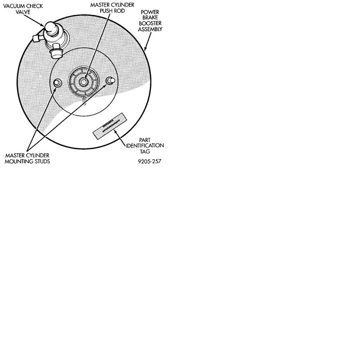
The power brake booster can be identified if required, by the tag attached to the body of the booster assembly (Fig. 1). This tag contains the following information. The production part number of the power booster assembly, the date it was built and who manufactured it.
The power brake booster assembly is not a repairable part and must be replaced as a complete unit if it is found to be faulty in any way. The power booster vacuum check valve is not repairable but can be replaceable as an assembly.
The power brake booster in vacuum operated. The vacuum is supplied from the intake manifold on the engine through the power brake booster check valve (Fig. 2).
As the brake pedal is depressed, the power boosters input rod moves forward. This opens and closes valves in the power booster, creating a vacuum on one side of a diaphragm and allowing atmospheric
Fig. 1 Power Brake Booster Identification
pressure to enter on the other. This difference in pressure forces the output rod of the power booster out against the primary piston of the master cylinder. As the pistons in the master cylinder move forward this creates the hydraulic pressure in the brake system.