

5 - 4 BRAKES |
|
Ä |
|
SERVICE ADJUSTMENTS
INDEX
|
page |
Adjusting Rear Service Brakes . . . . . . . . . . . . . . |
. . 4 |
Bleeding Brake System . . . . . . . . . . . . . . . . . . . |
. . 6 |
Brake Hose and Tubing . . . . . . . . . . . . . . . . . . . |
. . 7 |
Master Cylinder Fluid Level . . . . . . . . . . . . . . . . |
. . 4 |
MASTER CYLINDER FLUID LEVEL
NON-ABS BRAKES
Check master cylinder reservoir brake fluid level a minimum of twice a year.
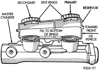
Master cylinder reservoirs are marked with the words fill to bottom of rings indicating proper fluid level (Fig. 1).
If necessary, add fluid to bring the level to the bottom of the primary reservoir split ring.
Use only Mopart brake fluid or an equivalent from a sealed container. Brake fluid must conform to DOT 3, specifications.
DO NOT use brake fluid with a lower boiling point, as brake failure could result during prolonged hard braking.
Use only brake fluid that was stored in a tightlysealed container.
DO NOT use petroleum-based fluid because seal damage in the brake system will result.
Fig. 1 Master Cylinder Fluid Level (Non-ABS)
ABS BRAKES
The hydraulic assembly is equipped with a plastic fluid reservoir with a filter/strainer in the filler neck of the reservoir.
The Anti-Lock brake system requires that the hydraulic accumulator be de-pressurized whenever checking the brake fluid level. To check the brake fluid level, the following procedure should be used:
|
page |
Stop Lamp Switch Adjustment (All Vehicles) |
. . . . . 12 |
Test for Fluid Contamination . . . . . . . . . . . . |
. . . . . . 7 |
Testing Application Adjuster Operation . . . . |
. . . . . . 5 |
Wheel Stud Nut Tightening . . . . . . . . . . . . . . |
. . . . . 7 |
(1)With the ignition off, de-pressurize the hydraulic accumulator by applying the brake pedal approximately 40 times, using a pedal force of approximately 220 N (50 lbs.). A noticeable change in pedal feel will occur when the accumulator is de-pressurized. Continue to apply the pedal several times after this change in pedal feel occurs to insure that the brake system is fully de-pressurized.
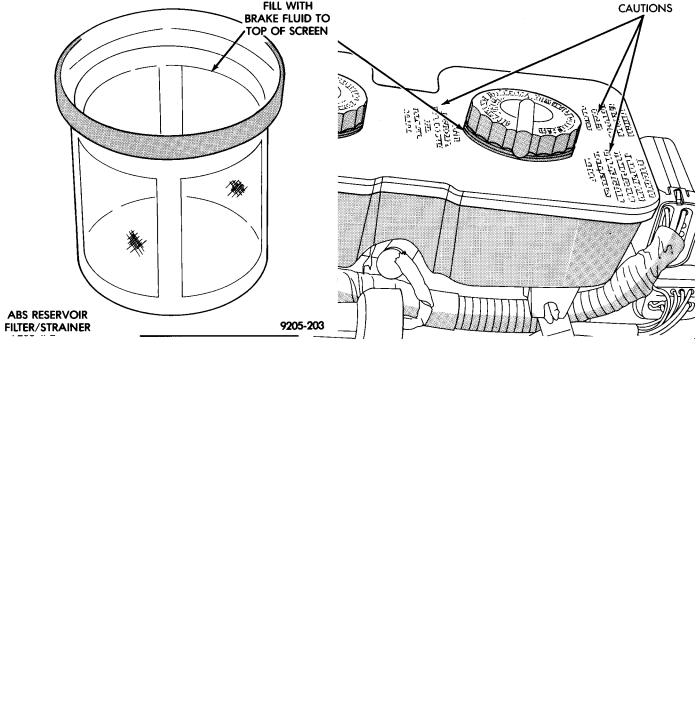
(2)Thoroughly clean both reservoir caps and surrounding area of reservoir, (Fig. 2) before removing caps. This is to avoid getting dirt into the reservoir and contaminating the brake fluid.
(3)Inspect the brake fluid to see if it is at the proper level, see instructions on top of reservoir. (FILL TO TOP OF WHITE SCREEN ON FRONT FILTER/STRAINER.)
(4)Fill reservoir with brake fluid to top of screen (Fig. 3) on the filter/strainer located in brake fluid reservoir. Only use brake fluid conforming to DOT 3 specifications such as Mopart or equivalent.
(5)Replace brake fluid reservoir caps.
ADJUSTING REAR SERVICE BRAKES
Normally, self adjusting drum brakes will not require manual brake shoe adjustment. Although in the event of a brake reline it is advisable to make the initial adjustment manually to speed up the adjusting time.
(1)Raise the vehicle so all wheels are free to turn. See Hoisting Recommendations in the Lubrication And Maintenance Section, at the front of this service manual.
(2)Remove rear brake adjusting hole rubber plug (Fig. 4), from the rear brake shoe support plate.
(3)Be sure parking brake lever is fully released. Then back off parking brake cable adjustment so there is slack in the cable.
(4)Insert Brake Adjuster, Special Tool C-3784, (Fig.
5)or equivalent through the adjusting hole in support plate and against star wheel of adjusting screw. Move handle of tool upward until a slight drag is felt when the road wheel is rotated.
(5)Insert a thin screwdriver or piece of welding rod into brake adjusting hole (Fig. 5). Push adjusting lever out of engagement with star wheel. Care should be taken so as not to bend adjusting le-
Ä |
|
BRAKES 5 - 5 |
|
Fig. 2 Master Cylinder Fluid Level (W/ABS)
Fig. 3 ABS Reservoir Fill Level On Filter/Strainer
ver or distort lever spring. While holding adjusting lever out of engagement with star wheel, back off star wheel to ensure a free wheel with no brake shoe drag.
(6)Repeat above adjustment at the other rear wheel. Install adjusting hole rubber plugs (Fig. 4) in rear brake supports.
(7)Adjust parking brake after wheel brake adjustment. See parking brake adjustment, under Parking Brakes in this group of the service manual.
Fig. 4 Brake Adjusting Hole Plug
It is important to follow the above sequence to avoid the possibility of the parking brake system causing brake drag. This could occur if the parking brakes are adjusted before the service brakes.
TESTING APPLICATION ADJUSTER OPERATION
Place the vehicle on a hoist with a helper in the driver's seat to apply the brakes. Remove the access plug from the rear adjustment slot in each brake