

Ä |
|
BRAKES 5 - 69 |
|
SERVICE PROCEDURES
POWER BRAKE BOOSTER ASSEMBLY
REMOVE
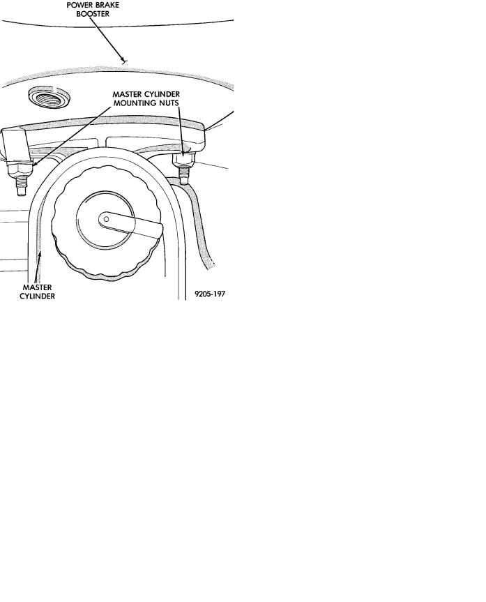
(1) Remove the 2 nuts (Fig. 4) attaching master cylinder assembly to power brake unit.
Fig. 2 Power Brake Booster Assembly
Different systems and engine combinations require different vacuum hose routings.
The power brake booster assembly mounts on the engine side of the dash panel. It is externally connected to the brake system by an input push rod to the brake pedal. A vacuum line connects the power booster to the intake manifold. The master cylinder is bolted to the front of the power brake booster assembly (Fig. 3).
Fig. 4 Master Cylinder Mounting
(2) Carefully slide master cylinder off mounting studs with brake lines attached, and allow the assembly to rest against fender shield.
(3) Disconnect vacuum hose from power brake booster check valve (Fig. 1). DO NOT REMOVE
CHECK VALVE FROM POWER BRAKE BOOSTER.
(4) From under instrument panel, position a small screwdriver between the center tang on the power brake booster input rod to brake pedal pin retaining clip.
(5) Rotate screwdriver enough to allow retainer clip center tang to pass over end of brake pedal pin and pull retainer clip off pin. Discard retainer clip it is not to be reused, replace only with a new retainer clip.
(6) Remove the four nuts that attach the power
brake booster to the vehicle dash panel. Nuts are Fig. 3 Power Brake Mounting accessible from under the dash panel in the area of
the steering column and pedal bracket (Fig. 5).