


Ä
mum braking performance. During brake pressure modulation, as brake pressure is increased, wheel slip is allowed to reach up to 30%. This means that the wheel rolling velocity is 30% less than that of a free rolling wheel at a given vehicle speed. This slip may result in some tire chirping, depending on the road surface. This sound should not be interpreted as total wheel lock-up.
Complete wheel lock-up normally leaves black tire marks on dry payment. However, Anti-Lock Braking will not leave dark black tire marks since the wheel never reaches a locked condition. Tire marks may however be noticeable as light patched marks.
ABS EQUIPPED VEHICLE PERFORMANCE
Anti-Lock Brakes provide the driver with some steering control during hard braking. However there are conditions where the system does not provide any benefit. In particular, hydroplaning is still possible when the tires ride on a film of water, resulting in the tire leaving the road surface rendering the vehicle almost uncontrollable. In addition, extreme steering maneuvers at high speed or high speed cornering beyond the limits of tire adhesion to the road surface may cause vehicle skidding, independent of vehicle braking. So, the ABS system is termed Anti-Lock instead of Anti-Skid.
One of the significant benefits of the ABS system is that of maintaining steering control during hard braking or during braking on slippery surfaces. It is therefore possible to steer the vehicle while braking on almost any road surface.
ABS SYSTEM SELF-DIAGNOSTICS
The ABS system has been designed with Self Diagnostic Capability. There are two self checks the systems performs every time the vehicle is started. First, when the key is turned on the system performs an electrical check called Start-Up Cycle. During this check, the Red Brake Warning Lamp and the Amber Anti-Lock Warning Lamp are illuminated. Then turned off at the end of the test, after about 1 to 2 seconds. When the vehicle reaches a speed of about 3 to 4 miles per hour. The system performs a functional check called Drive-Off. During Drive-Off. hydraulic valves are activated briefly to test their function. Drive-Off can be detected as a series of rapid clicks upon driving off the first time the car is started. If the brake pedal is applied during Drive-Off, the test is by-passed. Both of these conditions are a normal part of the system self test. Most fault conditions will set a ABS Fault Code in the (CAB), which can be retrieved to aid in fault diagnosis. Details can be found in Diagnosis Section.
ABS WARNING SYSTEMS OPERATION
The ABS system uses two methods for notifying the driver of a system malfunction. These include the
ANTI-LOCK 10 BRAKE SYSTEM 5 - 75
standard Red Brake Warning Lamp and an Amber Anti-Lock Warning Lamp, both located in the instrument cluster. The purpose of these two lamps are discussed in detail below.
RED BRAKE WARNING LAMP
The Red Brake Warning Lamp, located in the instrument cluster, will Turn On to warn the driver of brake system conditions that may result in reduced braking ability. The lamp is also turned on when the parking brake is not fully released. Conditions which may cause the Red Brake Warning Lamp to Turn On include:
²Parking brake not fully released. If the parking brake is applied or not fully released. The switch on the parking brake pedal assembly will ground the Red Brake Warning Lamp circuit and cause the lamp to turn on. On vehicles equipped with mechanical instrument clusters, the Amber Anti-Lock Lamp will turn on if the vehicle is driven above 3 miles per hour with the Parking Brake applied.
²Low brake fluid. The fluid level sensor in the hydraulic assembly reservoir will ground the Red Brake Warning Lamp circuit if low brake fluid level is detected. In addition, ABS will be deactivated above 3 miles per hour and the Amber Anti-Lock Warning Lamp will be illuminated. If the vehicle is equipped with EVIC, a low fluid condition will also cause the Low Brake Fluid message to appear.
²Low accumulator pressure. In the event of low accumulator pressure, the dual function pressure switch in the hydraulic assembly will signal the (CAB) to ground the Red Brake Warning Lamp circuit. This will cause the Red Brake Warning Lamp to turn on. Low accumulator pressure may result in loss of power assist.
²Hydraulic assembly or (CAB) faults. The hydraulic assembly or (CAB) may turn on the Red Brake Warning Lamp. If certain faults are detected in either the hydraulic assembly or the (CAB), or the normal brake system.
²Bulb check. As a bulb check, the Red Brake Warning Lamp will illuminate whenever the ignition switch is placed in the crank position.
Illumination of the red Brake Warning Lamp may indicate reduced braking ability. A vehicle that has the Red Brake Warning Lamp ON should not be driven except to do diagnostic procedures described in Section 2 of this manual. Most conditions that turn on the Red Brake Warning Lamp will also turn on the Amber Anti-Lock Warning Lamp, consequently disabling the Anti-Lock function.
ANTI-LOCK WARNING LAMP
The Anti-Lock Warning Lamp is located in the instrument cluster and is Amber in color. The Amber Anti-Lock Warning Lamp is illuminated when the

5 - 76 ANTI-LOCK 10 BRAKE SYSTEM
(CAB) detects a condition that results in a shutdown of Anti-Lock function. The Amber Anti-Lock Warning Lamp is normally on until the (CAB) completes its self tests and turns the lamp off. For example, if the (CAB) is disconnected, the lamp is on.
Display of the Amber Anti-Lock Warning Lamp without the Red Brake Warning Lamp indicates only that Anti-Lock function has been disabled. Power assisted normal braking is unaffected.
NORMAL OPERATION OF WARNING LAMPS
With the ignition in the Crank position, the Red Brake Warning Lamp will turn on as a bulb check. The Amber Anti-Lock Warning Lamp will turn on for as little as 1 second to as long as 30 seconds.
If the car has not been started for several hours, for example after sitting overnight. The Red Brake Warning Lamp and the Amber Anti-Lock Warning Lamp may both be turned on for as long as 60 seconds after turning the ignition on. This condition is caused by the loss of accumulator charge when the vehicle is parked for extended periods, particularly in cold weather. When the key is then turned on. The Pump/Motor assembly must recharge the hydraulic accumulator to its normal operating pressure. As recharging is completed, both warning lamps will turn off when accumulator pressure reaches about (1,000
Ä
psi). Both lamps should remain off at all other times, indicating normal operation.
ANTI-LOCK BRAKE SYSTEM COMPONENTS
The following is a detailed description of the AntiLock Brake System components. For information on servicing the other Non-ABS related components that may be referred to in this section. See the Standard Brakes Section that refers to the specific component.
HYDRAULIC ASSEMBLY
The ABS system uses an integral Hydraulic Assembly (Fig. 1) which includes a Booster/Master Cylinder, Modulator, Hydraulic Bladder Accumulator and Fluid Reservoir. The Hydraulic Assembly is located on the dash panel cowl on the drivers side of the vehicle. The following is a description of the components that make up the Hydraulic Assembly.
HYDRAULIC ASSEMBLY BRAKE FLUID RESERVOIR
A one piece Fluid Reservoir is attached to the hydraulic assembly with rubber seals. The Fluid Reservoir (Fig. 1) is internally separated into three fluid sections. Most of the brake fluid is contained in the Fluid Reservoir and hydraulic bladder accumulator (Fig. 1) Additional fluid is contained in the pump/motor assembly accumulator.
Fig. 1 Hydraulic Assembly
Ä |
|
ANTI-LOCK 10 BRAKE SYSTEM 5 - 77 |
|
BOOSTER/MASTER CYLINDER
The Booster/Master Cylinder portion of the hydraulic assembly is an integral component and should never be disassembled.
The Booster/Master Cylinder uses a diagonally split configuration during normal braking. The two circuits are hydraulically isolated so a leak or malfunction in one circuit will allow continued braking ability in the other.
When force is applied to the brake pedal, the input pushrod applies force to the boost control valve. As the boost control valve is moved, it allows the pressurized fluid from the accumulator to flow into the master cylinder booster chamber. The pressure generated in the booster chamber is directly proportioned to the brake pedal force exerted by the driver. This pressure in the booster servo in turn applies pressure to the primary master cylinder piston that in turn applies pressure to the secondary master cylinder piston. The pressure generated in the primary and secondary circuits are used to apply the brakes during normal braking.
WARNING: THE HYDRAULIC ACCUMULATORS CONTAIN BRAKE FLUID AND NITROGEN GAS AT HIGH PRESSURE. CERTAIN PORTIONS OF THE BRAKE SYSTEM ALSO CONTAIN BRAKE FLUID AT HIGH PRESSURE. REMOVAL OR DISASSEMBLY MAY RESULT IN PERSONAL INJURY AND IMPROPER SYSTEM OPERATION. REFER TO THE APPROPRIATE SERVICE MANUAL FOR PROPER SERVICE PROCEDURES.
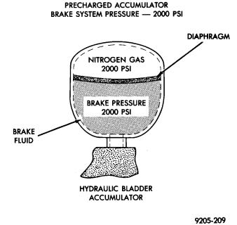
HYDRAULIC BLADDER ACCUMULATOR
A Hydraulic Bladder Accumulator (Fig. 2) is used to store brake fluid at high pressure. The pressurized fluid is used for Anti-Lock operation and for power assisted normal braking. The accumulator uses an elastomeric bladder configuration with a nitrogen precharge of about 6,895 kPa (1,000 psi). With no brake fluid in the system, the nitrogen gas pre-charge applies approximately 6,895 kPa (1,000 psi) to one side of the diaphragm (Fig. 2).
Under normal operation, the Pump/Motor assembly charges the accumulator to an operating pressure of between 11,032 and 13,790 kPa (1600 psi to 2,000 psi). As pressurized brake fluid enters the accumulator, pushing against the opposite side of the diaphragm, (Fig. 2) the nitrogen gas is compressed and increases in pressure.
DUAL FUNCTION PRESSURE SWITCH
The Dual Function Pressure Switch is located on the bottom of the hydraulic assembly (Fig. 1) and monitors Accumulator Pressure. The Dual Function Pressure Switch, if found to be functioning improperly using the ABS diagnostics, can be replaced. See
Fig. 2 Hydraulic Fluid Accumulator
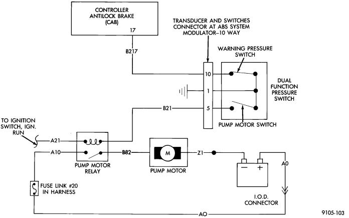
service procedure in Electronic Components area of On Car ABS Service in this section of the service manual. The primary function is to control operation of the Pump/Motor assembly and thus maintain proper accumulator operating pressure. When accumulator pressure falls to or below 11,032 kPa (1600 psi) the pump motor switch (internal to the dual function pressure switch) will close. This provides a ground, through Pin 1 of the Transducer and Switch, 10 way electrical connector to the Pump/Motor relay coil. The energized coil pulls the relay contacts closed, providing battery voltage to run the Pump/Motor. When Accumulator Pressure reaches 13,790 kPa (2,000 psi) the switch opens, de-energizing the Pump/Motor Relay that turns off the Pump/Motor.
NOTE: THE (CAB) DOES NOT REGULATE OR CONTROL ACCUMULATOR PRESSURE.
The second purpose of the Dual Function Pressure Switch is to provide a signal to the (CAB) when the Accumulator Pressure falls below 6,895 kPa (1,000 psi). A Warning Pressure Switch, internal to the Dual Function Pressure Switch, is normally closed above 6,895 kPa (1,000 psi). This sends a ground signal to pin 17 at the (CAB). At or below 6,895 kPa (1,000 psi) the Warning Pressure Switch opens. Internally, the (CAB) (pin 17) detects 12 volts and thus low pressure. At this warning pressure, the (CAB) will disable the Anti-Lock Braking functions, light the Red Brake Warning Lamp and the Amber Anti-Lock Warning Lamp. After two minutes of continuous detection, a low accumulator fault is stored.
Grounding for the Dual Function Pressure Switch. Is provided through Pin 1 of the Transducer and Switch, 10 way electrical connector and the Modulator Assembly.
5 - 78 ANTI-LOCK 10 BRAKE SYSTEM |
|
Ä |
|
DUAL FUNCTION PRESSURE SWITCH WIRING DIAGRAM
PRESSURE TRANSDUCERS
Two Pressure Transducers are used for brake system fault detection. Both transducers generate a voltage signal (between 0.25 volts and 5.0 volts) that is proportional to pressure. These signals are compared by the (CAB) and used to detect brake system faults that would require Anti -Lock Braking to be disabled.
The Boost Pressure Transducer is mounted on the bottom of the hydraulic assembly, (Fig. 1) and monitors booster servo pressure. The Primary Pressure Transducer is mounted on the left side of the hydraulic assembly and monitors primary master cylinder pressure.
DIFFERENTIAL PRESSURE SWITCH
A non-latching Differential Pressure Switch is used to detect a pressure difference greater than 2,068 kPa (300 psi.) between the primary and secondary master cylinder hydraulic circuits. If detected, the Differential Pressure Switch grounds the output of the primary pressure transducer (circuit B-218). This results in a 0.0 volt signal from the Primary Pressure Transducer that is sensed by the (CAB) as a differential pressure fault. The (CAB) will then light the Red Brake Warning Lamp and the Amber Anti-
Lock Warning Lamp and disable the Anti-Lock braking function. See Fig. 1 for location of the differential pressure switch.
PROPORTIONING VALVES
The ABS system uses screw-in Proportioning Valves in place of the conventional Height Sensing Proportioning Valve. Each rear brake circuit has its own screw-in Proportioning Valve that is attached to the rear brake outlet ports of the hydraulic assembly (Fig. 1). These valves limit brake pressure to the rear brakes after a certain brake pressure is reached. This improves front to rear wheel brake balance during normal braking.
FILTERS-SERVICEABILITY
There is a screen filter in each of the two master cylinder fill ports. There is also a low pressure filter for the pump/motor. The filter is integral to the Pump/Motor low pressure hose.
FLUID LEVEL SWITCH
A Low Fluid Switch is located in the hydraulic assembly fluid reservoir, (Fig. 1). The switch consists of a float and magnetic reed switch that closes when low fluid is detected. The Low Fluid Switch is used as an input, to the Red Brake Warning Lamp, the (CAB), and the EVIC (if so equipped). When a low