

5 - 100 ANTI-LOCK 10 BRAKE SYSTEM |
|
Ä |
|
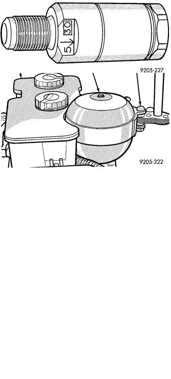
Fig. 16 Remove And Install Bladder Accumulator
(4)Turn ignition switch to the run position to energize the pump/motor assembly and pressurize hydraulic system. Check for leakage at the hydraulic assembly to hydraulic bladder accumulator fitting.
(5)Again de-pressurize the accumulator by pumping the brake pedal a minimum of 40 times as described in De-Pressurizing Hydraulic Accumulator in this section of the manual.
(6)Then check the brake fluid level in the hydraulic assembly reservoir. If brake fluid level is low, fill reservoir to proper level (Fig. 15) with Mopart brake fluid or equivalent conforming to DOT 3 requirements.
PROPORTIONING VALVES (FIG. 17)
Fig. 17 ABS Proportioning Valve
CAUTION: Proportioning valves should never be disassembled or repaired in any way, repair is by replacement only.
REMOVE
(1) De-pressurize the hydraulic accumulator by pumping the brake pedal a minimum of 40 times.
Using the procedure as described in De-Pressurizing Hydraulic Accumulator listed earlier in this section.
WARNING: FAILURE TO DE-PRESSURIZE THE HYDRAULIC ASSEMBLY/ACCUMULATOR PRIOR TO PERFORMING THIS OPERATION, MAY RESULT IN PERSONAL INJURY AND/OR DAMAGE TO PAINTED SURFACES OF THE VEHICLE.
(2)Remove fresh air intake ducts and air cleaner.
(3)Remove pressure and return hose (Fig. 5) from hydraulic unit. (See Pressure and Return Hose Section For Proper Removal Procedure.)
(4)Remove brake tube from the proportioning valve that requires servicing.
(5)Remove proportioning valve requiring service from the hydraulic assembly (Fig. 18).
INSTALL
(1)Install proportioning valve on hydraulic assembly and tighten to 40 NIm (30 ft. lbs.) torque.
(2)Install brake tube on proportioning valve. Tighten tube nut to 16 NIm (145 in. lbs.) torque.
(3)Install hydraulic pressure and return hoses.
Torque pressure hose to hydraulic assembly fitting to 16 NIm (145 in. lbs). Torque return hose to metal tube hose clamp to 1 NIm (10 in. lbs.).
(4)Install fresh air intake duct and air cleaner.
(5)Bleed the affected brake line, see Bleeding Brake System in this section.
ELECTRONIC COMPONENTS
CONTROLLER ANTI-LOCK BRAKE (CAB)
REMOVAL
(1)Turn vehicle ignition off.
(2)Raise vehicle on hoist, (CAB) access for removal is from the underside of the vehicle (Fig. 19).
(3)Remove transmission oil cooler line routing clip.
(4)Disconnect the wiring harness 60 way connector from the Controller Anti-Lock Brake Module (CAB).
VERIFY THAT THE VEHICLE IGNITION IS OFF BEFORE REMOVING THE 60 WAY CONNECTOR.
(5)Remove the 3 (CAB) module to frame rail mounting bolts.
(6)Remove the (CAB) module from the vehicle.
INSTALLATION
(1)Install the (CAB) module back in the vehicle.
(2)Install the 3 (CAB) module to frame rail attach-
ing bolts. Torque the 3 (CAB) module to frame rail attaching bolts to 5 NIm (40 in. lbs.).
(3)VERIFY THAT THE VEHICLE IGNITION IS OFF BEFORE CONNECTING THE 60 WAY CONNECTOR. Connect the wiring harness 60 way
Ä |
|
ANTI-LOCK 10 BRAKE SYSTEM 5 - 101 |
|
Fig. 18 Hydraulic Assembly
PUMP/MOTOR RELAY (FIG. 9)
Fig. 19 Location Controller Anti-Lock Brake (CAB)
connector into the (CAB) module until it is fully seated. Torque the 60 way connector to (CAB) module retaining bolt to 12 NIm (105 in. lbs.).
REMOVE/INSTALL
See (Fig. 9) Power Distribution Center. Find the location of the pump/motor relay in the (PDC). Remove pump/motor relay by pulling upward and install by pushing firmly into position. Do not twist the relay when removing or installing it.
See (Fig. 10) Relay and Warning Lamp Section of this group for the location of the Anti-Lock system relay and the Yellow Lamp relay. Remove the relay from the vehicle using the following procedure.
(1)Disconnect the wiring harness connectors from the relays. Connectors are removed from the relays by disengaging the connector locking tab from relay and pulling strait off relay, do not twist.
(2)Then remove the relay pack to inner fender attaching bolt.
The Anti-Lock system and Yellow Lamp relay are installed using the following procedure.
(1)Mount the relay pack to the inner fender with the anti-rotation tab on the bracket around lip of inner fender hole (Fig. 10) Relay and Warning Lamp Section of this group.
(2)Install the relay pack to inner fender mounting bolt and torque to 4 NIm (35 in. lbs.).
(3)Connect the wiring harness connectors onto the relays until the locking tabs on the connectors and

5 - 102 ANTI-LOCK 10 BRAKE SYSTEM |
|
Ä |
|
FRONT WHEEL SPEED SENSOR
REMOVAL
(1) Raise vehicle and remove front wheel and tire assembly.
(2) Remove screw from clip (Fig. 11) that holds sensor assembly grommet into fender shield.
Fig. 9 Pump/Motor Relay
relays are fully engaged. Do not twist connectors when installing them on the relays.
WHEEL SPEED SENSORS
INSPECTION
Inspect tone wheels (Fig. 10) for any missing or broken teeth, this can cause erratic speed sensor signals.
Fig. 10 Tone Wheel (Typical)
Tone wheels should show no evidence of contact with the wheel speed sensor. If contact was made, determine cause and correct.
Excessive runout of the tone wheels can cause erratic wheel speed sensor signals. Replace assembly if runout exceeds approximately 0.25 mm (0.010 inch).
Fig. 11 Front Wheel Speed Sensor Routing
(3)Carefully, pull sensor assembly grommet from fender shield. When removing grommet from fender shield, do not pull on speed sensor cable.
(4)Unplug speed sensor cable connector, from vehicle wiring harness.
(5)Remove the 2 screws (Fig. 11) that secure the speed sensor cable, routing tube to the fender well.
(6)Remove the 2 sensor assembly grommets from the retainer bracket, on the strut damper (Fig. 11).
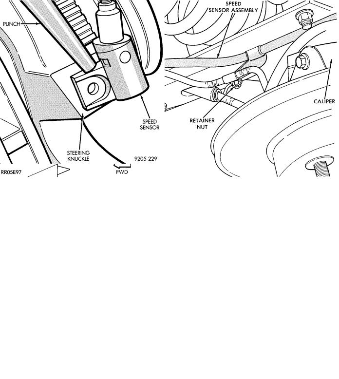
(7)Remove speed sensor assembly to steering knuckle attaching bolt (Fig. 11).
(8)Carefully, remove sensor head from steering knuckle. If the sensor has seized, due to corrosion, use a hammer and punch to tap edge of sensor ear
Ä |
|
ANTI-LOCK 10 BRAKE SYSTEM 5 - 103 |
|
(Fig. 12), rocking the sensor side to side until free.
DO NOT USE PLIERS ON SENSOR HEAD.
Fig. 12 Removing Speed Sensor (Typical)
INSTALLATION
(1)Connect the wheel speed sensor cable connector, to the vehicle wiring harness.
(2)Push sensor assembly grommet into hole in
fender shield. Install clip and screw (Fig. 11). Torque screw to 4 NIm (35 in. lbs.).
(3)Install speed sensor cable grommets in bracket on strut damper (Fig. 11).
(4)Install speed sensor cable routing tube to fender well (Fig. 11). Torque both screws to 4 NIm (35 in. lbs.).
(5)Coat the speed sensor with High Temperature Multi-purpose E.P. Grease before installing into the
steering knuckle. Install speed sensor attaching screw and tighten to 7 NIm (60 in. lbs.).
CAUTION: Proper installation of wheel speed sensor cables is critical to continued system operation. Be sure that cables are routed correctly and installed in all retainers. Failure to properly route and install cables in retainers, as shown in this section. May result in contact with moving parts and/or over extension of cables, resulting in an open circuit.
Fig. 13 Rear Wheel Speed Sensor Routing at Trailing Arm