


Ä
MECHANICAL DIAGNOSTICS AND SERVICE PROCEDURES
SPECIAL SERVICE TOOL
Some diagnostic procedures in this section require the use of the DRB II diagnostics tester. The proper application and procedures for the use of this tool are described below.
DRB II DIAGNOSTIC TESTER
Some of the diagnostic procedures that are explained in this section require the use of the DRB II Diagnostics Tester to insure that proper diagnostics are performed. Refer to those sections for proper testing procedures and the DRB II operators manual for its proper operational information.
INTERMITTENT FAULTS
As with virtually any electronic system, intermittent faults in the ABS system may be difficult to accurately diagnose.
Most intermittent faults are caused by faulty electrical connections or wiring. When an intermittent fault is encountered, check suspect circuits for:
(1)Poor mating of connector halves or terminals not fully seated in the connector body.
(2)Improperly formed or damaged terminals. All connector terminals in a suspect circuit should be carefully reformed to increase contact tension.
(3)Poor terminal to wire connection. This requires removing the terminal from the connector body to inspect.
(4)Pin presence in the connector assembly.
If a visual check does not find the cause of the problem, operate the car in an attempt to duplicate the condition and record the Fault code.
Most failures of the ABS system will disable AntiLock function for the entire ignition cycle even if the fault clears before key-off. There are some failure conditions, however, which will allow ABS operation to resume during the ignition cycle in which a failure occurred. If the failure conditions are no longer present. The following conditions may result in intermittent illumination of the Amber Anti-Lock Warning Lamp. All other failures will cause the lamp to remain on until the ignition switch is turned off. Circuits involving these inputs to the (CAB) should be investigated if a complaint of intermittent warning system operation is encountered.
(1)Low system voltage. If Low System Voltage is detected by the (CAB), the (CAB) will turn on the Amber Anti-Lock Warning Lamp until normal system voltage is achieved. Once normal voltage is seen at the (CAB), normal operation resumes.
(2)Anti-Lock relay. If the relay fails to make the ground circuit connection or is an intermittent ground. The (CAB) will turn on the Amber Anti-Lock Warning Light.
ANTI-LOCK 6 BRAKE SYSTEM 5 - 117
(3) Excess decay, an extended pressure decay period, will turn on the Amber Anti-Lock Warning Light until the vehicle comes to a complete stop.
Additionally, any condition which results in interruption of power to the (CAB) or modulator assembly may cause the Amber Anti-Lock Warning Lamp to turn on intermittently.
ABS BRAKE SYSTEM DIAGNOSTIC FEATURES
ABS SYSTEM SELF DIAGNOSIS
The ABS system is equipped with a self diagnostic capability which may be used to assist in isolation of ABS faults. The features of the self diagnostics system are described below.
START-UP CYCLE
The self diagnostic ABS start up cycle begins when the ignition switch is turned to the on position. An electrical check is completed on the ABS components. Such as Wheel Speed Sensor Continuity and System and other Relay continuity. During this check the Amber Anti-Lock Light is turned on for approximately 1- 2 seconds.
Further Functional testing is accomplished once the vehicle is set in motion.
²The solenoid valves and the pump/motor are activated briefly to verify function.
²The voltage output from the wheel speed sensors is verified to be within the correct operating range.
If the vehicle is not set in motion within 3 minutes from the time the ignition switch is set in the on position. The solenoid test is bypassed but the pump/motor is activated briefly to verify that it is operating correctly.
CONTROLLER ANTI-LOCK BRAKE (CAB)
Fault codes are kept in a Non-Volatile memory until either erased by the technician using the DRB II or erased automatically after 50 ignition cycles (key ONOFF cycles). The only fault that will not be erased after 50 (KEY CYCLES) is the (CAB) fault. A (CAB) fault can only be erased by the technician using the DRB II diagnostic tester. More than one fault can be stored at a time. The number of key cycles since the most recent fault was stored is also displayed. Most functions of the (CAB) and ABS system can be accessed by the technician for testing and diagnostic purposes by using the DRB II.
LATCHING VERSUS NON-LATCHING ABS FAULTS
Some faults detected by the (CAB) are latching; the fault is latched and (ABS) is disabled until the ignition switch is reset. Thus ABS is disabled even if the original fault has disappeared. Other faults are nonlatching; any warning lights that are turned on, are only turned on as long as the fault condition exists.

5 - 118 ANTI-LOCK 6 BRAKE SYSTEM
As soon as the condition goes away, the Anti-Lock Warning Light is turned off. Although a fault code will be set in most cases.
BENDIX ABS SYSTEMS DIAGNOSTICS
The Bendix Anti-Lock 6 Brake System Diagnostics, beyond the basic mechanical diagnostics, systems and components covered earlier in this section. Are accomplished by the use of the DRB II diagnostic tester. See testing procedures outlined in the Bendix Anti-Lock 6 Diagnostics Manual for the 1992 M.Y. vehicles.
Please refer to the above mentioned manual for any further electronic diagnostics and service procedures that are required on the Bendix Anti-Lock 6 Brake System.
ON-CAR ABS BRAKE SYSTEM SERVICE
GENERAL SERVICE PRECAUTIONS
The following are general cautions which should be observed when servicing the Anti-Lock brake system and/or other vehicle systems. Failure to observe these precautions may result in Anti-Lock Brake System component damage.
If welding work is to be performed on the vehicle, using an electric arc welder, the (CAB) connector should be disconnected during the welding operation.
The (CAB) connector should never be connected or disconnected with the ignition switch in the ON position.
Many components of the Anti-Lock Brake System are not serviceable and must be replaced as an assembly. Do not disassemble any component which is not designed to be serviced.
CHECKING BRAKE FLUID LEVEL
CAUTION: Only use brake fluid conforming to DOT 3 specifications, such as Mopar or Equivalent. Do not use any fluid which contains a petroleum base. Do not use a container which has been used for petroleum based fluids or a container which is wet with water. Petroleum based fluids will cause swelling and distortion of rubber parts in the hydraulic brake system. Water will mix with brake fluid, lowering the fluid boiling point. Keep all brake fluid containers capped to prevent contamination. Remove the front cap of the master cylinder reservoir and fill to the bottom of the split ring.
For the specific procedure for the inspection of brake fluid level and adding of brake to the reservoir. Refer to the Service Adjustments Section in this group of the service manual.
Ä
BLEEDING BENDIX ANTI-LOCK 6 BRAKE SYSTEM
The Anti-Lock Brake System must be bled anytime air is permitted to enter the hydraulic system, due to disconnection of brake lines, hoses of components.
If the Modulator Assembly is removed from the vehicle, both the Base Brake System and the AntiLock Brake System must be bled using the appropriate procedures. It is important to note that excessive air in the brake system will cause a soft or spongy feeling brake pedal.
During bleeding operations, be sure that the brake fluid level remains close to the FULL level in the reservoir. Check the fluid level periodically during the bleeding procedure and add DOT 3 brake fluid as required.
The Bendix Anti-Lock 6 Brake System must be bled as two independent braking systems. The non ABS portion of the brake system is to be bled the same as any non ABS system. Refer to the Service Adjustments section in this manual for the proper bleeding procedure to be used. This brake system can be either pressure bled or manually bled.
The Anti-Lock portion of brake system MUST be bled separately. This bleeding procedure requires the use of the DRB II Diagnostic tester and the bleeding sequence procedure outlined below.
ABS BLEEDING PROCEDURE (FIG. 1)
(1)Assemble and install all brake system components on vehicle making sure all hydraulic fluid lines are installed and properly torqued.
(2)Bleed the base brake system. Using the standard pressure or manual bleeding procedure as outlined in the Service Adjustments section of this service manual.
To perform the bleeding procedure on the ABS unit. The battery and acid shield must be removed from the vehicle. Reconnect the vehicles battery, to the vehicles positive and negative battery cables using jumper cables. This is necessary to allow access to the 4 bleeder screws located on the top of the Modulator assembly.
(3)Connect the DRB II Diagnostics Tester to the diagnostics connector. Located behind the Fuse Panel access cover on the lower section of the dash panel to the left of the steering column. (It is a blue 6 way connector).
(4)Using the DRB II check to make sure the (CAB) does not have any fault codes stored. If it does remove them using the DRB II.
Ä |
|
ANTI-LOCK 6 BRAKE SYSTEM 5 - 119 |
|
WARNING: WHEN BLEEDING THE MODULATOR ASSEMBLY WEAR SAFETY GLASSES. A CLEAR BLEED TUBE MUST BE ATTACHED TO THE BLEEDER SCREWS AND SUBMERGED IN A CLEAR CONTAINER FILLED PART WAY WITH CLEAN BRAKE FLUID. DIRECT THE FLOW OF BRAKE FLUID AWAY FROM THE PAINTED SURFACES OF THE VEHICLE. BRAKE FLUID AT HIGH PRESSURE MAY COME OUT OF THE BLEEDER SCREWS, WHEN OPENED.
When bleeding the Modulator Assembly. The following bleeding sequence MUST be followed to insure complete and adequate bleeding of the brakes hydraulic system. The Modulator Assembly can be bled using a Manual bleeding procedure or standard Pressure Bleeding Equipment.
If the brake system is to be bled using pressure bleeding equipment. Refer to Bleeding Brake System, in the Service Adjustments section at the beginning of this group, for proper equipment usage and procedures.
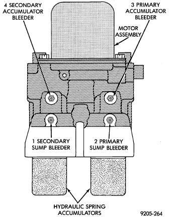
MODULATOR ASSEMBLY BLEEDING SEQUENCE
1 SECONDARY SUMP
(1)Put a bleeder tube on the Secondary Sump bleeder screw (Fig. 1).
(2)Use a pressure bleeder, or have an assistant, apply light and constant pressure on the brake pedal. Loosen the Secondary Sump bleeder screw (Fig. 1).
(3)Using the DRB II select the Actuate Valves test mode. Then actuate the LF Build/Decay Valve.
(4)Bleed the Secondary Sump. Until a clear air free flow of brake fluid is evident in the clear hose and no air bubbles appear in the container, or the brake pedal bottoms.
(5)Tighten the bleeder screw and release the brake pedal.
(6)Repeat steps 2 through 5 until a clear air free flow of brake fluid is coming out of the Secondary Sump bleeder screw.
(7)Next select and actuate the RR Build/Decay Valve. Again repeat steps 2 through 5 until a clean air free flow of brake fluid is coming out of the Secondary Sump bleeder screw.
2 PRIMARY SUMP
(1)Put a bleeder tube on the Primary Sump bleeder screw (Fig. 1).
(2)Use a pressure bleeder, or have an assistant, apply light and constant pressure on the brake pedal. Loosen the Primary Sump bleeder screw (Fig. 1).
(3)Using the DRB II select the Actuate Valves test mode. Then actuate the RF Build/Decay Valve.
(4)Bleed the Primary Sump. Until a clear air free flow of brake fluid is evident in the clear hose and no air bubbles appear in the container, or the brake pedal bottoms.
(5)Tighten the bleeder screw and release the brake pedal.
(6)Repeat steps 2 through 5 until a clear air free flow of brake fluid is coming out of the Primary Sump bleeder screw.
(7)Next select and actuate the LR Build/Decay Valve. Again repeat steps 2 through 5 until a clean air free flow of brake fluid is coming out of the Primary Sump bleeder screw.
Fig. 1 Bleeding ABS Modulator Assembly
3 PRIMARY ACCUMULATOR
(1)Put a bleeder tube on the Primary Accumulator bleeder screw (Fig. 1).
(2)Use a pressure bleeder, or have an assistant, apply light and constant pressure on the brake pedal. Loosen the Primary Accumulator bleeder screw (Fig. 1).
(3)Using the DRB II select the Actuate Valves test mode. Then actuate the RF/LR Isolation Valve.
(4)Bleed the Primary Accumulator. Until a clear air free flow of brake fluid is evident in the clear hose and no air bubbles appear in the container, or the brake pedal bottoms.
(5)Tighten the bleeder screw and release the brake pedal.
5 - 120 ANTI-LOCK 6 BRAKE SYSTEM
(6)Repeat steps 2 through 5 until a clear air free flow of brake fluid is coming out of the Primary Accumulator bleeder screw.
(7)Next select and actuate the RF Build/Decay Valve. Again repeat steps 2 through 5 until a clean air free flow of brake fluid is coming out of the Primary Accumulator bleeder screw.
4 SECONDARY ACCUMULATOR
(1)Put a bleeder tube on the Secondary Accumulator bleeder screw (Fig. 1).
(2)Use a pressure bleeder, or have an assistant, apply light and constant pressure on the brake pedal. Loosen the Secondary Accumulator bleeder screw (Fig. 1).
(3)Using the DRB II select the Actuate Valves test mode. Then actuate the LF/RR Isolation Valve.
(4)Bleed the Secondary Accumulator. Until a clear air free flow of brake fluid is evident in the clear hose and no air bubbles appear in the container, or the brake pedal bottoms.
(5)Tighten the bleeder screw and release the brake pedal.
(6)Repeat steps 2 through 5 until a clear air free flow of brake fluid is coming out of the Secondary Accumulator bleeder screw.
(7)Next select and actuate the LF Build/Decay Valve. Again repeat steps 2 through 5 until a clean air free flow of brake fluid is coming out of the Primary Accumulator bleeder screw.
Ä
PUMP/MOTOR SERVICE
On the Bendix Anti-Lock 6 Brake System the Pump/Motor assembly can only be serviced as part of Modulator Assembly.
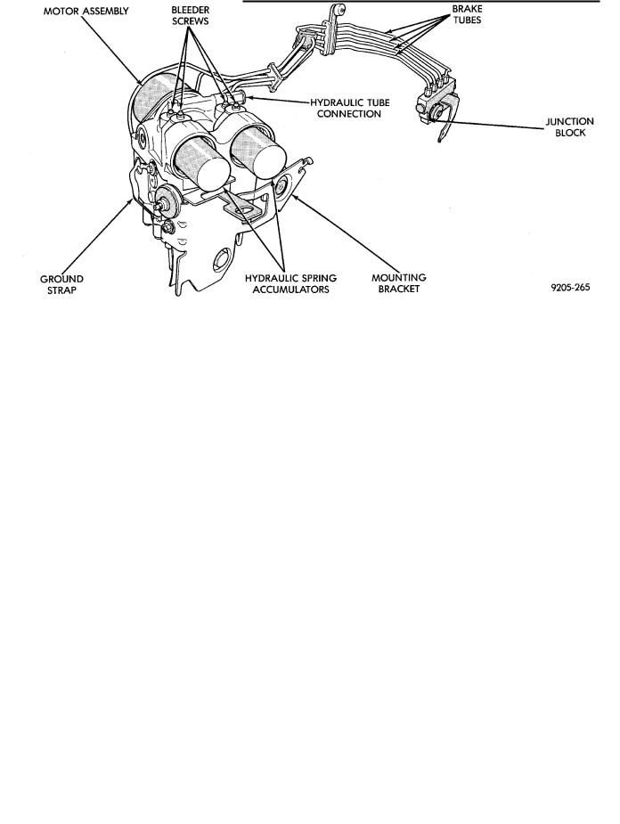
MODULATOR ASSEMBLY (FIG. 2)
REMOVAL
(1)Center vehicle on hoist, or raise front of vehicle on jack stands.
(2)Disconnect and remove the battery, battery tray and acid shield covering the modulator assembly (Fig. 2).
(3)Disconnect the delta (P) switch electrical connector from the Modulator Assembly (Fig. 3). Remove the top Modulator Assembly bracket to fender shield mounting bolt (Fig. 2).
(4)Disconnect the 2 master cylinder supply tubes at the Modulator Assembly. Loosen the 2 tubes at the Master Cylinder so the tubes can be swung out of the way without kinking them (Fig. 4).
(5)Raise the vehicle on the hoist.
(6)From under the vehicle disconnect the Modulator Assembly 10 way connector (Fig. 3). Remove the 4 remaining hydraulic brake tubes from the Modulator Assembly.
(7)(a) Remove the Modulator Assembly bracket mounting bolt closest to the junction block. (b) Loosen but do not fully remove the bracket mounting bolt nearest the radiator.
(8)Lower the vehicle, the Modulator Assembly and bracket can now be lifted out of the vehicle (Fig. 2).
Fig. 2 Modulator Assembly
Ä
Fig. 2 Modulator Assembly Removal
INSTALLATION
(1) Install the Modulator Assembly in the vehicle. Use the protruding tab on the Modulator Assembly
ANTI-LOCK 6 BRAKE SYSTEM 5 - 121
Fig. 3 Modulator Assembly Electrical Connections
to locate and hold the assembly in place in the vehicle. Make sure the bracket is held by the front mounting bolt.
(2) Install but do not tighten the Modulator Assembly bracket to fender shield attaching bolt.
Fig. 4 Brake Tube and Hose Routing at Modulator Assembly