

Ä |
|
ANTI-LOCK 10 BRAKE SYSTEM 5 - 85 |
|
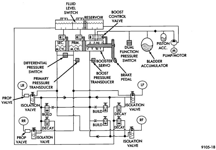
Fig. 11 Normal Braking - Hydraulic Control
ABS HYDRAULIC CIRCUITS AND VALVE OPERATION
Through the following operation descriptions and diagrams. The function of the various hydraulic control valves in the ABS system will be described. The fluid control valves mentioned below, control the flow of pressurized brake fluid to the wheel brakes during the different modes of Anti-Lock Braking.
NORMAL BRAKING
ISOLATION VALVES
Open to primary and secondary master cylinder brake fluid supply (Fig. 11).
DECAY AND BUILD VALVES
Closed, not allowing for the build-up or release of brake fluid supply (Fig. 11).
The brake pedal is applied. The travel of the brake pedal closes primary, secondary and booster servo circuits from fluid supply at the fluid reservoir. Brake fluid from the primary and secondary circuits flows through the open isolation valves and applies the wheel brakes. Fluid from the booster servo circuit
does not flow to the wheel brakes. The fluid flow is blocked by the closed build valves and check valves.
POWER ASSIST
The boost control valve shuttles between its three positions to provide power assisted braking (Fig. 11).
ABS BRAKING-BUILD PRESSURE
ISOLATION VALVES
Closed, isolating wheel brakes from master cylinder primary and secondary fluid supplies and open to booster servo circuit pressure through open build valves (Fig. 12).
DECAY VALVES
Closed, not allowing the escape of pressurized fluid supply from the hydraulic system (Fig. 12).
BUILD VALVES
Open, allowing booster servo circuit pressure to flow to the wheel brakes through the isolation valves (Fig. 12).

5 - 86 ANTI-LOCK 10 BRAKE SYSTEM |
|
Ä |
|
|
Fig. 12 Build Pressure - Hydraulic Control |
POWER ASSIST |
ABS BRAKING-DECAY PRESSURE |
The boost control valve shuttles between its three positions to provide power assisted braking (Fig. 12).
ABS BRAKING-HOLD PRESSURE
For explanation purposes we will assume all speed sensors are sending the same wheel speed information, requiring the same modulation at the same rate.
ISOLATION VALVES
Closed, isolating the wheel brakes from the master cylinder primary and secondary fluid supplies. Build and decay valves are closed preventing any fluid from reaching the open isolation valves (Fig. 13).
DECAY AND BUILD VALVES
Closed, not allowing fluid supply to reach the open isolation valves (Fig. 13).
ISOLATION VALVES
Closed, isolating the wheel brakes from the master cylinder primary and secondary fluid supplies (Fig. 14).
DECAY VALVES
Open, allowing release of fluid pressure through decay valve to the fluid reservoir (Fig. 14).
BUILD VALVE
Closed, blocking booster servo circuit fluid to wheel brakes (Fig. 14).