

Ä |
|
ANTI-LOCK 6 BRAKE SYSTEM 5 - 113 |
|
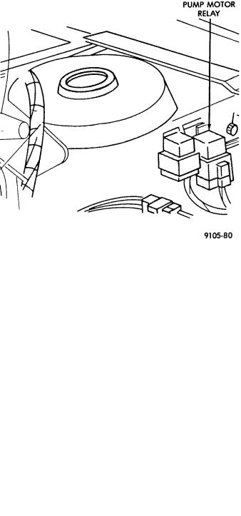
Fig. 10 Pump Motor Relay With Power Distribution
Center
Fig. 11 Pump Motor Relay W/O Power Distribution
Center
The (CAB) by itself, also has the ability to turn on the Amber Anti-Lock Warning Lamp. The (CAB) can turn on the Amber Anti-Lock Warning Lamp by providing a ground at pin 15.
ANTI-LOCK WARNING LAMP ON
System Relay and Anti-Lock Warning Lamp
Relay De-Energized.
When the Amber Anti-Lock Warning Lamp is on, there is no electrical current flow from the (CAB) at pin 57. The System Relay coil is NOT energized. No electrical current flows to pin 47 and 41 (modulator valve power), or to the Anti-Lock Warning Lamp Relay coil. Thus, the Amber Anti-Lock Warning Lamp is not energized. The Amber Anti-Lock Warning Lamp is grounded through the Anti-Lock Warning Lamp Relay contacts. The Amber Anti-Lock Warning Lamp is turned on.
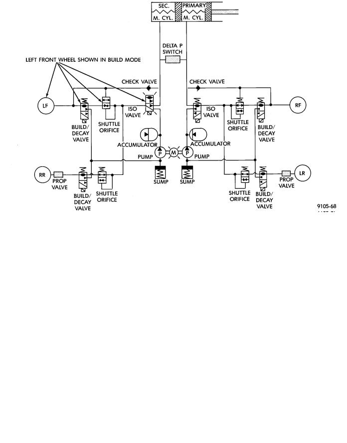
HYDRAULIC CIRCUITS AND VALVE OPERATION
Through the following operation descriptions and diagrams. The function of the various hydraulic control valves in the ABS system will be described. The fluid control valves mentioned below, control the flow of pressurized brake fluid to the wheel brakes during the different modes of Anti-Lock braking.
For explanation purposes we will assume all speed sensors are sending the same wheel speed information, requiring the same hydraulic fluid modulation at the same rate.
NORMAL BRAKING
ISOLATION VALVES
Open to primary and secondary master cylinder fluid supply (Fig. 1).
BUILD/DECAY VALVES
Closed (Fig. 1).
The brake pedal is applied. The travel of the brake pedal closes primary and secondary circuits from the master cylinder fluid supply. Brake fluid from the primary and secondary circuits flows through the open isolation valves, through the build/decay valves to the wheel brakes.
ABS BRAKING-BUILD PRESSURE
ISOLATION VALVES
Closed, isolating wheel brakes from master cylinder primary and secondary fluid supply. Through open build valves (Fig. 2).
BUILD/DECAY VALVES
Open (Fig. 2).
ABS BRAKING-DECAY PRESSURE
ISOLATION VALVES
Closed, isolating the wheel brakes from the master cylinder primary and secondary fluid supplies (Fig. 3).
5 - 114 ANTI-LOCK 6 BRAKE SYSTEM |
|
Ä |
|
Fig. 1 Normal Braking - Hydraulic Control
Fig. 2 Build Pressure - Hydraulic Control